Chapter Objectives
After reading this chapter, you'll be able to do the following:
Connect fields in a scene graph to each other
Create and use global fields in the database
Connect a variety of engines to fields and other engines in a scene graph
Disable engine connections temporarily
Create a simple engine network
Animate parts of a scene using engines
Use the rotor, blinker, shutter, and pendulum nodes to animate parts of a scene graph
This chapter describes engines, classes of Inventor objects that can be connected to fields in the scene graph and used to animate parts of the scene or to constrain certain elements of the scene to each other. It also describes how fields can be connected to engines and to other fields, and how to use and create global fields in the database.
In earlier chapters, you've created scene graphs with 3D objects that responded to user events. The 3D objects themselves were fixed, and they moved only in response to user interaction or to sensor activity. In this chapter, you'll learn about a new class of object, called engines, that allows you to encapsulate both motion and geometry into a single scene graph. Just as you would connect a real-world engine to other equipment to spin a flywheel or turn a fan belt, you “wire” engine objects into the scene database to cause animated movement or other complex behavior in the scene graph. Engines can also be connected to other engines so that they move or react in relation to each other, and eventually make changes to the Inventor database.
As a simple example, consider a scene graph that describes the geometry for a windmill. You can attach an engine object that describes the rotation of the windmill blades and performs an incremental rotation of the blades in response to time. This scene graph, including the engine, can be saved in an Inventor file. Whenever the scene graph is read in, the windmill is displayed and the blades animate. Both the geometry and the behavior are described by the nodes and engines in the scene graph.
A more complex example would involve wiring two objects together. For example, you might create a scene with a car whose motion is based on an engine object. A second engine could look at the car's motion and turn that information into camera motion so that the camera could follow the moving car. Or you might wire two engines together so that one engine affects the activity of the other engine. In the case of the windmill, you could connect a second engine in front of the rotation engine to filter time so that the windmill blades rotate only between the hours of nine in the morning and five at night.
In some cases, you could use either a sensor or an engine to create a certain effect. Table 13-1 compares sensors and engines to help you weigh the trade-offs between the two.
Table 13-1. Comparison of Sensors and Engines
Sensors | Engines |
|---|---|
Are part of the application (are not written to file) | Are part of the scene graph (can be read from file and written to file) |
Have user-defined callback functions | Have built-in functions |
Allow explicit control over order of firing | Are evaluated automatically |
Can be attached to any kind of field (field data sensors) | Have inputs and outputs of a fixed type |
Can affect objects outside the scene graph | Can affect only other nodes or engines in a scene graph |
Engines are generally used in two different ways:
To animate parts of a scene
To constrain one part of a scene in relation to some other part of the scene
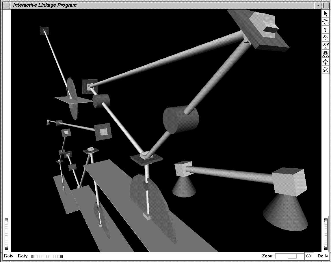
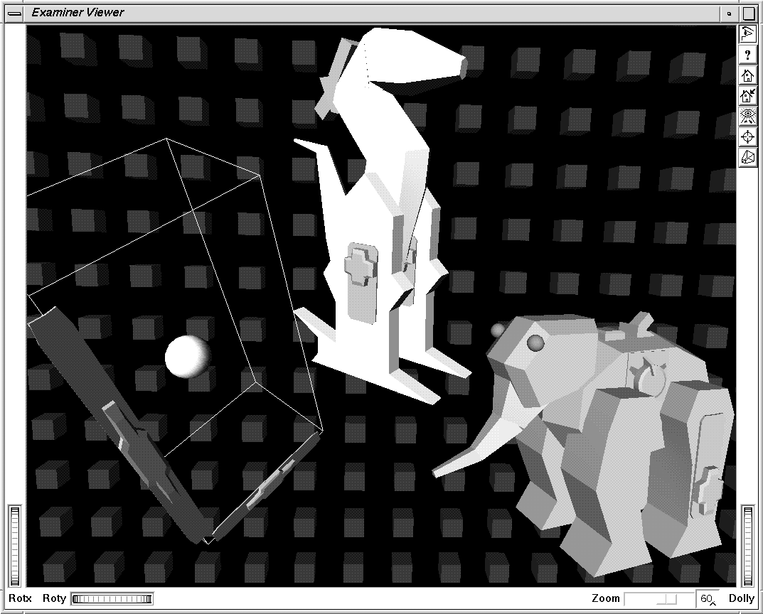
Figure 13-1 and Figure 13-2 show applications that use engines. In Figure 13-1, four different classes of links are created—struts, hinges, cranks, and double struts. Engines are used to connect links end-to-end. The objects in Figure 13-2 use engines to edit transform nodes that animate the animals and objects in the scene.
As shown in Example 13-1 later in this chapter, you can connect parts of a scene to a clock so that animation in the scene occurs in relation to changes in time. Example 13-6 shows an example of constraints, where the movement of an object is constrained to a set path.
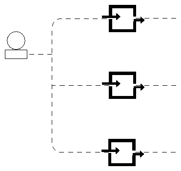
You can think of an engine as a black box that receives input values, performs some operation on them, and then copies the results into one or more outputs. Both the inputs and the outputs of the engine can be connected to other fields or engines in the scene graph. When an engine's output values change, those new values are sent to any fields or engines connected to them.
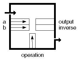
An engine, shown in Figure 13-3, has inputs derived from SoField and outputs derived from SoEngineOutput. Each engine evaluates a built-in function when its input values change. The resulting output values are then sent to all fields and engines connected to that engine. Because SoEngine is derived from the SoBase class, it includes methods for reading and writing to files.
For example, the engine shown in Figure 13-3 could represent SoComposeVec4f, an engine that creates an SoMFVec4f object. It has four inputs of type SoMFFloat and one output of type SoMFVec4f. This engine composes the four inputs into one SoMFVec4f output.
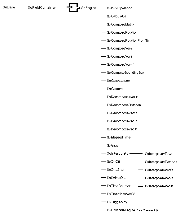
Figure 13-4 shows the class tree for engines, which can be grouped according to the kinds of operations they perform.
Arithmetic engines are as follows:
SoCalculator
SoBoolOperation
SoInterpolateFloat, SoInterpolateRotation, SoInterpolateVec2f, SoInterpolateVec3f, SoInterpolateVec4f
SoTransformVec3f
SoComposeVec2f, SoDecomposeVec2f
SoComposeVec3f, SoDecomposeVec3f
SoComposeVec4f, SoDecomposeVec4f
SoComposeRotation, SoDecomposeRotation
SoComposeMatrix, SoDecomposeMatrixSoComputeBoundingBox
Animation engines are as follows:
SoElapsedTime
SoOneShot
SoTimeCounter
Triggered engines are as follows:
SoCounter
SoOnOff
SoTriggerAny
SoGate
Use the connectFrom() method on SoField to connect a field to another field or engine. When you connect fields of different types, the value of the input field is automatically converted to the new output field type. The syntax for connecting a field is as follows:
void connectFrom(SoField *field);
void connectFrom(SoEngineOutput *engineOutput);
For example, to connect the orientation field in an SoPerspective camera to the rotation field of an SoTransform:
xform->rotation.connectFrom(&pCamera->orientation); |
To connect the SoElapsedTime engine to the string field of an SoText3 node:
yourText->string.connectFrom(&elapsedTime->timeOut); |
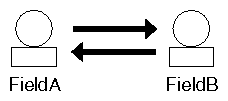
Suppose you connect two fields as shown in Figure 13-5. In this example, the top arrow indicates that fieldA is the source field and fieldB is the destination field. The bottom arrow indicates that fieldB is the source field and fieldA is the destination field. Once you have set up this connection, whenever you change fieldA, fieldB changes. When you change fieldB, fieldA changes. You may be concerned that you've set up an infinite loop where the two fields continuously update each other. Actually, when the value in fieldA changes, fieldB changes. At this point, fieldA knows that it has already been changed and does not change again.
Use the disconnect() method to break a field connection (on the destination field), and use the isConnected() method to query whether a connection exists. Methods such as setValue() can also be called on a field that is connected from another field or engine. Whoever sets the field value last, wins.
The term engine network refers to the collection of engines and fields that are “wired together” in the scene graph. When planning larger engine networks, you may sometimes consider having multiple connections to a field or engine. The rule to follow is that a given field or engine can have only one incoming connection, but it can have multiple outgoing connections. Figure 13-6 illustrates this principle.
If you call connectFrom() on a field or engine that has already been connected from a different source, the original connection is broken and the new connection is made.
When you connect fields of different types, Inventor automatically converts values from one type to another. It performs the following conversions when necessary:
Any field type to String
String to any field type
Between any two of Bool, Float, Long, Short, ULong, UShort
Between Color and Vec3f
Between Float and Time
Between Matrix and Rotation
Between Name and Enum
Between Rotation and Vec4f (quaternion)
From an MF field to its SF version, and from an SF field to its MF version
Multiple-step conversions are not supported—that is, although you can convert directly from a Vec4f to a Rotation and a Rotation to a Matrix, you cannot convert from a Vec4f to a Matrix.
If your program tries to connect a field to a field or engine output of a different type and no conversion between the types exists, the connection will not be made and a debugging error will occur. See The Inventor Toolmaker for details on how to create your own field converter.
Reference counting for engines is similar to that for nodes. Field-to-field connections, including connections from an engine's input to a field, do not increment any reference counts. Each engine-output-to-field connection increments the engine's reference count by 1. Similarly, removing an engine output's field connection decrements its reference count. If the last connection is removed, the reference count for that engine goes to 0 and it is deleted. To preserve the engine when you are disconnecting it, reference it. Also, be aware that field connections are broken when the node or engine containing the field is deleted. This, in turn, could cause a connected engine to be deleted as well.
To temporarily disable a field connection, call enableConnection(FALSE) on the destination field or call enable(FALSE) on the engine output.
This method is useful when you want to temporarily disable a large engine network. If you disconnect the field from the engine, that engine might be unreferenced to 0, and then mistakenly deleted. Disabling a field connection does not affect the engine's reference count. Use the isConnectionEnabled() method to query whether a connection has been enabled.
When you change one value in an engine network, you can assume that all other values that depend on this value are updated at once. In fact, for efficiency, fields and inputs are marked when they are out of date, but they are updated only when their values are used. A complicated engine network, for example, could be connected to an unselected child of a switch group and never used. In this case, its values could be marked as needing to be updated but never actually reevaluated because the engine network is never traversed.
Some engines, such as the gate and animation engines, can selectively control when their values are updated. Many of these engines use a field of type SoSFTrigger that updates the output value one time only when the field is touched. See “Gate Engine” for more information.
Global fields are fields in the Inventor database that you can access by name and that are not contained in any specific node or engine. One built-in global field is provided: the realTime global field, which is of type SoSFTime. This field contains the current real-clock time and can be connected to fields or engines to create clock-based animation. You can create additional global fields as required. If you were creating a key-frame animation editor, for example, you might want to create a “current frame” field that could be connected to various engines. Once the field is created, you use the standard field methods to connect it to other parts of the scene graph.
Use the createGlobalField() method of SoDB to create a global field:
static SoField *SoDB::createGlobalField(const SbName &name,
SoType type);
There can be only one global field with a given name. If there is already a field with the given name and type, it is returned. If there is already a field with the given name, but it is of an incompatible type, NULL is returned.
The getGlobalField() method returns the global field with the given name:
static SoField *SoDB::getGlobalField(const SbName &name);
The type of the returned field can be checked using the field class's getTypeId() method. For example,
if (globalField->isOfType(SoSFFloat::getClassTypeId()) ... |
An example of using the realTime global field is
engineA->input1.connectFrom(SoDB::getGlobalField("realTime"));
|
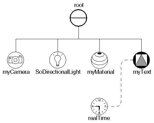
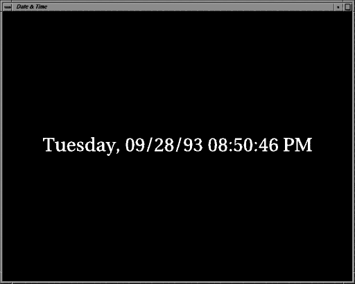
Example 13-1 creates a digital clock that connects an SoText3 string to the realTime global field. Figure 13-7 shows the scene graph for this example. Figure 13-8 shows the digital clock.
#include <Inventor/SoDB.h> #include <Inventor/Xt/SoXt.h> #include <Inventor/Xt/SoXtRenderArea.h> #include <Inventor/nodes/SoDirectionalLight.h> #include <Inventor/nodes/SoMaterial.h> #include <Inventor/nodes/SoPerspectiveCamera.h> #include <Inventor/nodes/SoSeparator.h> #include <Inventor/nodes/SoText3.h> |
main(int , char **argv)
{
   // Initialize Inventor and Xt
   Widget myWindow = SoXt::init(argv[0]);
   if (myWindow == NULL)
      exit(1);

   SoSeparator *root = new SoSeparator;
   root->ref();

   // Add a camera, light, and material
   SoPerspectiveCamera *myCamera = new SoPerspectiveCamera;
   root->addChild(myCamera);
   root->addChild(new SoDirectionalLight);
   SoMaterial *myMaterial = new SoMaterial;
   myMaterial->diffuseColor.setValue(1.0, 0.0, 0.0);
   root->addChild(myMaterial);

   // Create a Text3 object, and connect to the realTime field
   SoText3 *myText = new SoText3;
   root->addChild(myText);
   myText->string.connectFrom(SoDB::getGlobalField("realTime"));

   SoXtRenderArea *myRenderArea = new SoXtRenderArea(myWindow);
   myCamera->viewAll(root, myRenderArea->getSize());
   myRenderArea->setSceneGraph(root);
   myRenderArea->setTitle("Date & Time");
   myRenderArea->show();

   SoXt::show(myWindow);
   SoXt::mainLoop();
}
|
The following engines can be used to animate objects in the scene graph. Each of these engines has a timeIn field, which is connected automatically to the realTime global field when the engine is constructed. This field can, however, be connected to any other time source.
The elapsed-time engine is a basic controllable time source. You can start, stop, reset, pause, and control the speed of this engine. If you pause it (by setting the pause field to TRUE), it stops updating its timeOut field, but it keeps counting internally. When you turn off the pause, it jumps to its current position without losing time.
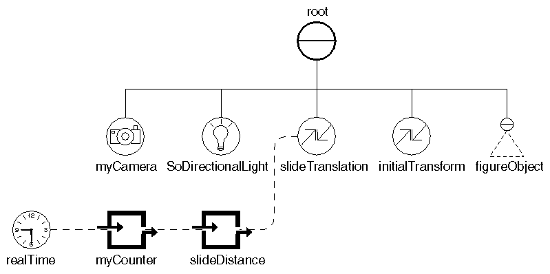
Example 13-2 uses the output from an elapsed time engine to control the translation of a figure. The resulting effect is that the figure slides across the scene. Figure 13-9 shows the scene graph for this example. The timeOut output of the elapsed time engine (myCounter) is connected to an SoComposeVec3f engine (slideDistance). This second engine inserts the timeOut value into the x slot of a vector. Once the value is in vector format, it can be connected to the translation field of the slideTranslation node.
Note that the timeOut value is an SoSFTime, but the SoComposeVec3f engine requires inputs of type SoSFFloat. Inventor performs this conversion automatically for you, converting the time to a number of seconds.
   // Set up transformations
   SoTranslation *slideTranslation = new SoTranslation;
   root->addChild(slideTranslation);
   SoTransform *initialTransform = new SoTransform;
   initialTransform->translation.setValue(-5., 0., 0.);
   initialTransform->scaleFactor.setValue(10., 10., 10.);
   initialTransform->rotation.setValue(SbVec3f(1,0,0), M_PI/2.);
   root->addChild(initialTransform);

   // Read the figure object from a file and add to the scene
   SoInput myInput;
   if (!myInput.openFile("jumpyMan.iv"))
      return (1);
   SoSeparator *figureObject = SoDB::readAll(&myInput);
   if (figureObject == NULL)
      return (1);
   root->addChild(figureObject);

   // Make the X translation value change over time.
   SoElapsedTime *myCounter = new SoElapsedTime;
   SoComposeVec3f *slideDistance = new SoComposeVec3f;
   slideDistance->x.connectFrom(&myCounter->timeOut);
   slideTranslation->translation.connectFrom(
            &slideDistance->vector);
|
The SoOneShot engine is started when its trigger input is touched (with either touch() or setValue()). It runs for the specified duration, updating its timeOut field until it reaches the duration time. The ramp output, a float value from 0.0 (when the trigger starts) to 1.0 (when the duration is reached), is provided as a convenience. For example, the ramp output of a one-shot engine could be connected to the alpha input of a rotation interpolation to make a door open.
This engine has two flags stored in an SoSFBitMask field. The Retriggerable flag specifies whether to start the cycle over if a trigger occurs in the middle of a cycle. If this flag is not set (the default), the trigger is ignored and the cycle is finished. If this flag is set, the cycle restarts when a trigger occurs.
The Hold_Final flag specifies what happens at the end of the cycle. If this flag is not set (the default), all outputs return to 0 when the cycle finishes. If this flag is set, the isActive output returns to 0, but ramp and timeOut stay at their final values.
The SoTimeCounter engine counts from a minimum count (min) to a maximum count (max). The value for step indicates how the timer counts (the default is in increments of 1). The frequency input specifies the number of min-to-max cycles per second.
Unlike the one-shot and elapsed-time engines, the time-counter engine does not output a time; it outputs the current count. Each time the time counter starts a cycle, it triggers its syncOut output. This output can be used to synchronize one of the triggered engines with some other event.
Example 13-3 uses the output from two time-counter engines to control the horizontal and vertical motion of a figure. The resulting effect is that the figure jumps across the screen.
This example creates three engines, as shown in Figure 13-10. The output of the jumpWidthCounter (a time counter engine) is connected to the x input of the jump engine (an SoComposeVec3f engine). The output of the jumpHeightCounter (another time counter engine) is connected to the y input of the jump engine. The jump engine composes a vector using the x and y inputs, and then feeds this vector into the translation field of the jumpTranslation node. Figure 13-11 shows scenes from this example.
// Set up transformations
SoTranslation *jumpTranslation = new SoTranslation;
root->addChild(jumpTranslation);
SoTransform *initialTransform = new SoTransform;
initialTransform->translation.setValue(-20., 0., 0.);
initialTransform->scaleFactor.setValue(40., 40., 40.);
initialTransform->rotation.setValue(SbVec3f(1,0,0), M_PI/2.);
root->addChild(initialTransform);

// Read the man object from a file and add to the scene
SoInput myInput;
if (!myInput.openFile("jumpyMan.iv"))
   return (1);
SoSeparator *manObject = SoDB::readAll(&myInput);
if (manObject == NULL)
   return (1);
root->addChild(manObject);
|
// Create two counters, and connect to X and Y translations. // The Y counter is small and high frequency. // The X counter is large and low frequency. // This results in small jumps across the screen, // left to right, again and again and again. SoTimeCounter *jumpHeightCounter = new SoTimeCounter; SoTimeCounter *jumpWidthCounter = new SoTimeCounter; SoComposeVec3f *jump = new SoComposeVec3f; jumpHeightCounter->max = 4; jumpHeightCounter->frequency = 1.5; jumpWidthCounter->max = 40; jumpWidthCounter->frequency = 0.15; jump->x.connectFrom(&jumpWidthCounter->output); jump->y.connectFrom(&jumpHeightCounter->output); jumpTranslation->translation.connectFrom(&jump->vector); |
This section discusses the gate engine, which provides a convenient mechanism for selectively copying values from input to output. It also introduces the enable field and the trigger field, used by other engines.
By default, each time a value in an engine network changes, the new value propagates through the network. If a value is constantly changing, however, you may not want this change to propagate continuously through the scene graph. In this case, you might want to sample the value at regular intervals, or update the value only when a certain event occurs. Use the gate engine to control when such values are sent to the rest of the scene graph.
When you construct the gate engine, you pass in the type of its input and output fields. This type must be the type of a multiple-value field. (If you want to gate a single-value field, just pass in the corresponding multiple-
value type and Inventor will automatically convert it.) Other engines with similar constructors are SoSelectOne and SoConcatenate.
SoGate has these two inputs:
| enable (SoSFBool) | allows continuous flow of updated values | |
| trigger (SoSFTrigger) |
|
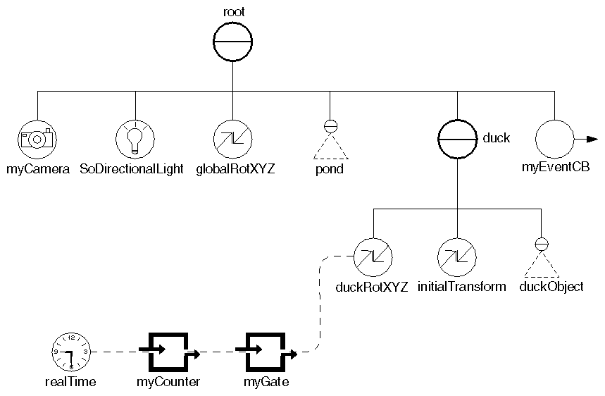
When the enable field is TRUE, data is allowed to be copied to the engine output each time a new value is received as input. To send only one value to the engine output, set the enable field to FALSE and use the trigger field to send the value. When the trigger field is touched, one value is sent. The trigger field is touched by calling either touch() or setValue() on it. Example 13-4 connects an elapsed time engine (myCounter) to a gate engine (myGate). Pressing the mouse button enables and disables the gate engine, which in turn controls the motion of a duck in the scene. The scene graph for this example is shown in Figure 13-12.
// Duck group
SoSeparator *duck = new SoSeparator;
root->addChild(duck);

// Read the duck object from a file and add to the group
SoInput myInput;
if (!myInput.openFile("duck.iv"))
   return (1);
SoSeparator *duckObject = SoDB::readAll(&myInput);
if (duckObject == NULL)
   return (1);

// Set up the duck transformations
SoRotationXYZ *duckRotXYZ = new SoRotationXYZ;
duck->addChild(duckRotXYZ);
SoTransform *initialTransform = new SoTransform;
initialTransform->translation.setValue(0., 0., 3.);
initialTransform->scaleFactor.setValue(6., 6., 6.);
duck->addChild(initialTransform);

duck->addChild(duckObject);

// Update the rotation value if the gate is enabled.
SoGate *myGate = new SoGate(SoMFFloat::getClassTypeId());
SoElapsedTime *myCounter = new SoElapsedTime;
myGate->input->connectFrom(&myCounter->timeOut);
duckRotXYZ->axis = SoRotationXYZ::Y;  // rotate about Y axis
duckRotXYZ->angle.connectFrom(myGate->output);

// Add an event callback to catch mouse button presses.
// Each button press will enable or disable the duck motion.
SoEventCallback *myEventCB = new SoEventCallback;
myEventCB->addEventCallback(
         SoMouseButtonEvent::getClassTypeId(),
         myMousePressCB, myGate);
root->addChild(myEventCB);

...

// This routine is called for every mouse button event.
void
myMousePressCB(void *userData, SoEventCallback *eventCB)
{
   SoGate *gate = (SoGate *) userData;
   const SoEvent *event = eventCB->getEvent();
   // Check for mouse button being pressed
   if (SO_MOUSE_PRESS_EVENT(event, ANY)) {

      // Toggle the gate that controls the duck motion
      if (gate->enable.getValue())
         gate->enable.setValue(FALSE);
      else
         gate->enable.setValue(TRUE);

      eventCB->setHandled();
   }
}
|
By convention, all inputs and outputs for the arithmetic engines in Inventor are multiple-value (MF) fields. If you supply a value of type SoSF, it is automatically converted to an MF field. Another important feature is that if you supply an array of values for one of the inputs, the output will also be an array (an MF value). If an engine has more than one input, some inputs may have more values than others. For example, input1 might have five values and input2 might have only three values. In such cases, the last value of the field with fewer values is repeated as necessary to fill out the array. (Here, the third value of input2 would be repeated two more times.)
As shown in Figure 13-13, the Boolean engine, SoBoolOperation, has two Boolean inputs (a and b) and one SoSFEnum input (operation) that describes the operation to be performed.
The value for operation can be one of the following:
Operation | Output Is TRUE If |
|---|---|
CLEA R
| never TRUE |
SET | always TRUE |
A | A is TRUE |
NOT_A | A is FALSE |
B | B is TRUE |
NOT_B | B is FALSE |
A_OR_B | A is TRUE or B is TRUE |
NOT_A_OR_B | A is FALSE or B is TRUE |
A_OR_NOT_B | A is TRUE or B is FALSE |
NOT_A_OR_NOT_B | A is FALSE or B is FALSE |
A_AND_B | A and B are TRUE |
NOT_A_AND_B | A is FALSE and B is TRUE |
A_AND_NOT_B | A is TRUE and B is FALSE |
NOT_A_AND_NOT_B | A and B are FALSE |
A_EQUALS_B | A equals B |
A_NOT_EQUALS_B | A does not equal B |
This engine has two outputs, output and inverse. The inverse field is TRUE if output is FALSE, and vice versa. If either of the inputs contains an array of values (they are of type SoMFBool), the output will also contain an array of values.
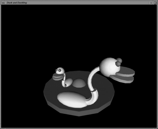
Example 13-5 modifies Example 13-4 and adds a Boolean engine to make the motion of the smaller duck depend on the motion of the larger duck. The smaller duck moves when the larger duck is still. Figure 13-14 shows an image created by this example.
// Bigger duck group
SoSeparator *bigDuck = new SoSeparator;
root->addChild(bigDuck);
SoRotationXYZ *bigDuckRotXYZ = new SoRotationXYZ;
bigDuck->addChild(bigDuckRotXYZ);
SoTransform *bigInitialTransform = new SoTransform;
bigInitialTransform->translation.setValue(0., 0., 3.5);
bigInitialTransform->scaleFactor.setValue(6., 6., 6.);
bigDuck->addChild(bigInitialTransform);
bigDuck->addChild(duckObject);

// Smaller duck group
SoSeparator *smallDuck = new SoSeparator;
root->addChild(smallDuck);
SoRotationXYZ *smallDuckRotXYZ = new SoRotationXYZ;
smallDuck->addChild(smallDuckRotXYZ);
SoTransform *smallInitialTransform = new SoTransform;
smallInitialTransform->translation.setValue(0., -2.24, 1.5);
smallInitialTransform->scaleFactor.setValue(4., 4., 4.);
smallDuck->addChild(smallInitialTransform);
smallDuck->addChild(duckObject);

// Use a gate engine to start/stop the rotation of
// the bigger duck.
SoGate *bigDuckGate =
         new SoGate(SoMFFloat::getClassTypeId());
SoElapsedTime *bigDuckTime = new SoElapsedTime;
bigDuckGate->input->connectFrom(&bigDuckTime->timeOut);
bigDuckRotXYZ->axis = SoRotationXYZ::Y;
bigDuckRotXYZ->angle.connectFrom(bigDuckGate->output);

// Each mouse button press will enable/disable the gate
// controlling the bigger duck.
SoEventCallback *myEventCB = new SoEventCallback;
myEventCB->addEventCallback(
         SoMouseButtonEvent::getClassTypeId(),
         myMousePressCB, bigDuckGate);
root->addChild(myEventCB);

// Use a Boolean engine to make the rotation of the smaller
// duck depend on the bigger duck.  The smaller duck moves
// only when the bigger duck is still.
SoBoolOperation *myBoolean = new SoBoolOperation;
myBoolean->a.connectFrom(&bigDuckGate->enable);
myBoolean->operation = SoBoolOperation::NOT_A;

SoGate *smallDuckGate = new
         SoGate(SoMFFloat::getClassTypeId());
SoElapsedTime *smallDuckTime = new SoElapsedTime;
smallDuckGate->input->connectFrom(&smallDuckTime->timeOut);
smallDuckGate->enable.connectFrom(&myBoolean->output);
smallDuckRotXYZ->axis = SoRotationXYZ::Y;
smallDuckRotXYZ->angle.connectFrom(smallDuckGate->output);
|
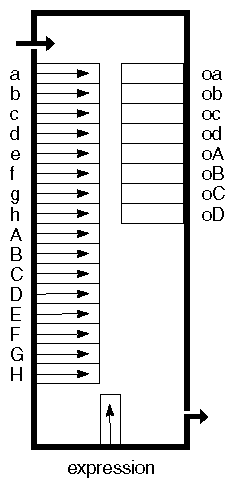
The calculator engine, SoCalculator, is similar to the Boolean engine, but it handles a wider range of operations and has more inputs and outputs. As shown in Figure 13-13, this engine has the following inputs and outputs:
Inputs | SoMFFloat | a, b, c, d, e, f, g, h |
| SoMFVec3f | A, B, C, D, E, F, G, H |
| SoMFString | expression |
|
|
|
Outputs | SoEngineOutput | oa, ob, oc, od (SoMFFloat) |
| SoEngineOutput | oA, oB, oC, oD (SoMFVec3f) |
The expression input, shown at the bottom of the engine, is of type SoMFString and is of the form:
“lhs = rhs”
lhs (lefthand side) can be any one of the outputs or a temporary variable. This engine provides eight temporary floating-point variables (ta – th) and eight temporary vector variables (tA – tH).
rhs (righthand side) supports the following operators:
Type of Operator | Example |
|---|---|
Binary operators | + - * / < > >= <= == != && || |
Unary operators | - ! |
Ternary operator | cond ? trueexpr : falseexpr |
Parentheses | ( expr ) |
Vector indexing | vec [int] |
Functions | func( expr, ... ) |
Terms | integer or floating-point constants; named constants such as MAXFLOAT, MINFLOAT, M_LOG2E, M_PI; the names of the calculator engine's inputs, outputs, and temporary variables (a, b, A, B, oa, ob, ta, tb, tA, tB, and so on) |
See the Open Inventor C++ Reference Manual for detailed information on using these operators.
Here is a simple example of using the calculator engine. It uses the following inputs and outputs:
Inputs | Outputs |
|---|---|
2 vectors (A, B) | oA (f times the negation of the cross product of A and B) |
2 scalars (a, f) | oa (convert a from degrees to radians) |
To specify the expression for a calculator engine called calc, the code would be
calc->expression.set1Value(0, "oa = a * M_PI / 180"); calc->expression.set1Value(1, "oA = -f * cross(A, B)"); |
Multiple expressions are evaluated in order, so a variable assigned a value in an earlier expression can be used in the righthand side of a later expression. Several expressions can be specified in one string, separated by semicolons.
The expressions can also operate on arrays. If one input contains fewer values than another input, the last value is replicated as necessary to fill out the array. All the expressions will be applied to all elements of the arrays. For example, if input a contains multiple values and input b contains the value 1.0, then the expression “oa = a + b” will add 1 to all of the elements in a.
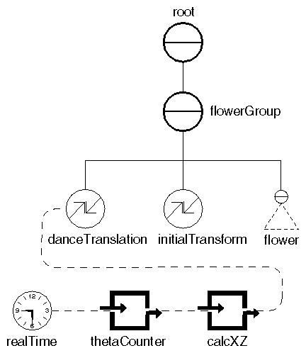
Example 13-6 shows using the calculator engine to move a flower along a path. The calculator engine computes a closed, planar curve. The output of the engine is connected to the translation applied to a flower object, which then moves along the path of the curve. Figure 13-16 shows the scene graph for this example. The dancing flower is shown in Figure 13-17.
// Flower group
SoSeparator *flowerGroup = new SoSeparator;
root->addChild(flowerGroup);

// Read the flower object from a file and add to the group
if (!myInput.openFile("flower.iv"))
   exit(1);
SoSeparator *flower= SoDB::readAll(&myInput);
if (flower == NULL)
   exit(1);

// Set up the flower transformations
SoTranslation *danceTranslation = new SoTranslation;
SoTransform *initialTransform = new SoTransform;
flowerGroup->addChild(danceTranslation);
initialTransform->scaleFactor.setValue(10., 10., 10.);
initialTransform->translation.setValue(0., 0., 5.);
flowerGroup->addChild(initialTransform);
flowerGroup->addChild(flower);
|
// Set up an engine to calculate the motion path: // r = 5*cos(5*theta); x = r*cos(theta); z = r*sin(theta) // Theta is incremented using a time counter engine, // and converted to radians using an expression in // the calculator engine. SoCalculator *calcXZ = new SoCalculator; SoTimeCounter *thetaCounter = new SoTimeCounter; thetaCounter->max = 360; thetaCounter->step = 4; thetaCounter->frequency = 0.075; calcXZ->a.connectFrom(&thetaCounter->output); calcXZ->expression.set1Value(0, "ta=a*M_PI/180"); // theta calcXZ->expression.set1Value(1, "tb=5*cos(5*ta)"); // r calcXZ->expression.set1Value(2, "td=tb*cos(ta)"); // x calcXZ->expression.set1Value(3, "te=tb*sin(ta)"); // z calcXZ->expression.set1Value(4, "oA=vec3f(td,0,te)"); danceTranslation->translation.connectFrom(&calcXZ->oA); |
Engines are usually connected to nodes. You can, though, create a node class that has built-in engines automatically connected to it. Here are some examples that Inventor provides. These nodes provide a convenient mechanism for adding animation to a scene graph:
SoRotor is a transformation node that spins the rotation angle while keeping the axis constant.
SoPendulum is a transformation node that oscillates between two rotations.
SoShuttle is a transformation node that oscillates between two translations.
SoBlinker is a switch node that cycles through its children.
Let's look at examples of rotor and blinker nodes.
The SoRotor node, derived from SoRotation, changes the angle of rotation at a specified speed. You can use an SoRotor node any place you would use an SoRotation. It has these fields:
| rotation (SoSFRotation) |
| |
| speed (SoSFFloat) | specifies the number of cycles per second. | |
| on (SoSFBool) | TRUE to run, FALSE to stop. The default is TRUE. |
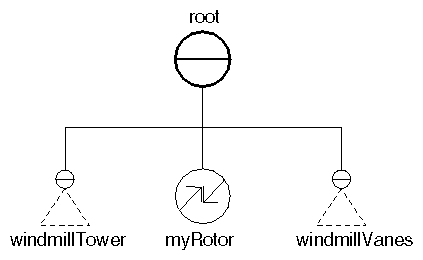
The number of times a second it is updated depends on the application. This node contains an engine that is connected to the real-time global field. Example 13-7 illustrates how you could use this node to rotate the vanes of a windmill. It specifies the rotation and speed for the rotor node and adds it to the scene graph before the windmill vanes, as shown in Figure 13-18. The rotation axis of the windmill vanes is (0.0, 0.0, 1.0) and the initial angle is 0.0. This rotation angle is updated automatically by the rotor node.
#include <Inventor/SoDB.h>
#include <Inventor/SoInput.h>
#include <Inventor/Xt/SoXt.h>
#include <Inventor/Xt/viewers/SoXtExaminerViewer.h>
#include <Inventor/nodes/SoSeparator.h>
#include <Inventor/nodes/SoRotor.h>

SoSeparator *
readFile(const char *filename)
{
   // Open the input file
   SoInput mySceneInput;
   if (!mySceneInput.openFile(filename)) {
      fprintf(stderr, "Cannot open file %s\n", filename);
      return NULL;
   }
|
   // Read the whole file into the database
   SoSeparator *myGraph = SoDB::readAll(&mySceneInput);
   if (myGraph == NULL) {
      fprintf(stderr, "Problem reading file\n");
      return NULL;
   }

   mySceneInput.closeFile();
   return myGraph;
}

main(int, char **argv)
{
   // Initialize Inventor and Xt
   Widget myWindow = SoXt::init(argv[0]);

   SoSeparator *root = new SoSeparator;
   root->ref();

   // Read in the data for the windmill tower
   SoSeparator *windmillTower =
            readFile("windmillTower.iv");
   root->addChild(windmillTower);

   // Add a rotor node to spin the vanes
   SoRotor *myRotor = new SoRotor;
   myRotor->rotation.setValue(SbVec3f(0, 0, 1), 0); // z axis
   myRotor->speed = 0.2;
   root->addChild(myRotor);

   // Read in the data for the windmill vanes
   SoSeparator *windmillVanes =
            readFile("windmillVanes.iv");
   root->addChild(windmillVanes);

   // Create a viewer
   SoXtExaminerViewer *myViewer =
            new SoXtExaminerViewer(myWindow);

   // Attach and show viewer
   myViewer->setSceneGraph(root);
   myViewer->setTitle("Windmill");
   myViewer->show();

   // Loop forever
   SoXt::show(myWindow);
   SoXt::mainLoop();
}
|
The SoBlinker node, derived from SoSwitch, cycles among its children by changing the value of the whichChild field. This node has the following fields:
| whichChild (SoSFLong) |
| |
| speed (SoSFFloat) | cycles per second. | |
| on (SoSFBool) | TRUE to run, FALSE to stop. The default is TRUE. |
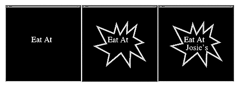
When it has only one child, SoBlinker cycles between that child (0) and SO_SWITCH_NONE. Example 13-8 shows how you could make the text string “Eat at Josie's” flash on and off.
// Add the non-blinking part of the sign to the root root->addChild(eatAt); // Add the fast-blinking part to a blinker node SoBlinker *fastBlinker = new SoBlinker; root->addChild(fastBlinker); fastBlinker->speed = 2; // blinks 2 times a second fastBlinker->addChild(josie); // Add the slow-blinking part to another blinker node SoBlinker *slowBlinker = new SoBlinker; root->addChild(slowBlinker); slowBlinker->speed = 0.5; // 2 secs per cycle; 1 on, 1 off slowBlinker->addChild(frame); |
