#include <Inventor/nodes/SoTextureCoordinate2.h>
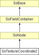
Inheritance diagram for SoTextureCoordinate2::

Public Methods | |
| SoTextureCoordinate2 (void) | |
| virtual void | doAction (SoAction *action) |
| virtual void | GLRender (SoGLRenderAction *action) |
| virtual void | callback (SoCallbackAction *action) |
| virtual void | pick (SoPickAction *action) |
Static Public Methods | |
| void | initClass (void) |
Public Attributes | |
| SoMFVec2f | point |
Protected Methods | |
| virtual | ~SoTextureCoordinate2 () |
When encountering nodes of this type during traversal, the coordinates it contains will be put on the state stack. Some shape nodes (for instance SoIndexedFaceSet, among many others) can then use these coordinates for explicit, detailed control of how textures are mapped to it's surfaces.
(If texturemapping is used without any SoTextureCoordinate2 nodes in the scenegraph leading up to a shape node, all shape types have default fallbacks. So SoTextureCoordinate2 nodes are only necessary to use if you are not satisfied with the default mapping.)
Note that an SoTextureCoordinate2 node will replace the coordinates already present in the state (if any).
Here's a very simple example (in Inventor scenegraph file format -- mapping it to sourcecode is straightforward) that shows how to set up two quadratic polygons, one mapped 1:1 to the texture, the other using only the upper left quarter of the texture:
Separator {
   Texture2 {
      image 6 8 3
      0x00ff0000 0x00ff0000 0x000000ff 0x000000ff 0x00ff00ff 0x00ff00ff
      0x00ff0000 0x00ff0000 0x000000ff 0x000000ff 0x00ff00ff 0x00ff00ff
      0x00ff0000 0x00ff0000 0x000000ff 0x000000ff 0x00ff00ff 0x00ff00ff
      0x0000ff00 0x0000ff00 0x0000ffff 0x0000ffff 0x0000ff00 0x0000ff00
      0x0000ff00 0x0000ff00 0x0000ffff 0x0000ffff 0x0000ff00 0x0000ff00
      0x00ffff00 0x00ffff00 0x000000ff 0x000000ff 0x00ffffff 0x00ffffff
      0x00ffff00 0x00ffff00 0x000000ff 0x000000ff 0x00ffffff 0x00ffffff
      0x00ffff00 0x00ffff00 0x000000ff 0x000000ff 0x00ffffff 0x00ffffff
   }

   Coordinate3 { point [ -1 -1 0, 1 -1 0, 1 1 0, -1 1 0 ] }

   # "1:1 mapping" to actual texture appearance. (Note that Y goes
   # from bottom to top, versus the common way of specifying bitmap
   # data from top to bottom.)
   TextureCoordinate2 { point [ 0 1, 1 1, 1 0, 0 0 ] }

   IndexedFaceSet {
      coordIndex [ 0, 1, 2, 3, -1 ]
      textureCoordIndex [ 0, 1, 2, 3, -1 ]
   }

   Translation { translation +4 0 0 }

   # Top left corner.
   TextureCoordinate2 { point [ 0 0.5, 0.5 0.5, 0.5 0, 0 0 ] }

   IndexedFaceSet {
      coordIndex [ 0, 1, 2, 3, -1 ]
      textureCoordIndex [ 0, 1, 2, 3, -1 ]
   }
}
|
|
Constructor. |
|
|
Destructor. |
|
|
Sets up initialization for data common to all instances of this class, like submitting necessary information to the Coin type system. Reimplemented from SoNode. |
|
|
This function performs the typical operation of a node for any action. Reimplemented from SoNode. |
|
|
Action method for the SoGLRenderAction. This is called during rendering traversals. Nodes influencing the rendering state in any way or who wants to throw geometry primitives at OpenGL overrides this method. Reimplemented from SoNode. |
|
|
Action method for SoCallbackAction. Simply updates the state according to how the node behaves for the render action, so the application programmer can use the SoCallbackAction for extracting information about the scene graph. Reimplemented from SoNode. |
|
|
Action method for SoPickAction. Does common processing for SoPickAction action instances. Reimplemented from SoNode. |
|
|
The set of 2D texture coordinates. Default value of field is an empty set. Texture coordinates should be specified on normalized coordinates, ie in the range [0, 1]. Origo is defined to be in the top-most, left-most corner (so note that Y coordinates is "flipped" versus the ordinary way of specifying data from bottom to top in bitmaps.) |
 1.2.9 written by Dimitri van Heesch,
© 1997-2001