Chapter Objectives
After reading this chapter, you'll be able to do the following:
Identify the key elements that constitute the Open Inventor toolkit
Explain the relationship of Open Inventor to OpenGL
Describe several ways to extend Open Inventor
This chapter describes the key elements in Open Inventor and briefly outlines how you can tailor your use of this toolkit to a particular set of needs. It explains how Inventor relates to programming tools you may already be familiar with, such as OpenGL and the X Window System. Most of the topics mentioned in this chapter are covered in detail in later chapters of this book.
The Inventor Mentor introduces graphics programmers and application developers to Open Inventor, an object-oriented 3D toolkit. Open Inventor is a library of objects and methods used to create interactive 3D graphics applications. Although it is written in C++, Inventor also includes C bindings.
Open Inventor is a set of building blocks that enables you to write programs that take advantage of powerful graphics hardware features with minimal programming effort. Based on OpenGL, the toolkit provides a library of objects that you can use, modify, and extend to meet new needs. Inventor objects include database primitives, including shape, property, group, and engine objects; interactive manipulators, such as the handle box and trackball; and components, such as the material editor, directional light editor, and examiner viewer.
Inventor offers the economy and efficiency of a complete object-oriented system. In addition to simplifying application development, Inventor facilitates moving data between applications with its 3D interchange file format. End users of 3D programs can cut and paste 3D scene objects and share them among a variety of programs on the desktop.
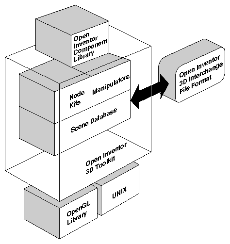
As shown in Figure 1-1, Inventor's foundation is supplied by OpenGL and UNIX. Inventor represents an object-oriented application policy built on top of OpenGL, providing a programming model and user interface for OpenGL programs.
The Inventor toolkit is window system–independent. A component library is helpful for using Inventor with specific window systems. This book describes one component library provided with the toolkit, which facilitates programming in Inventor using Xt windows and events. A companion to this book, The Inventor Toolmaker, provides details on how to extend Inventor to work with other window systems.
Inventor focuses on creating 3D objects. All information about these objects—their shape, size, coloring, surface texture, location in 3D space—is stored in a scene database. This information can be used in a variety of ways. The most common use is to display, or render, an image of the 3D objects on the screen.
For many 3D graphics packages, this image is the ultimate goal—a photorealistic representation on the screen of a 3D scene. But what if a user wants to move one of the objects to a different location, and perhaps view another object from a slightly different viewpoint? What if the user wants to experiment with a different range of colors for the objects and the background of the scene? What if a chemist wants to rearrange how two molecules align with each other? What if an airplane designer wants to redesign the curve of the airplane's wing? If the image exists only as a drawing on the screen, the programmer must write complicated code to implement these functions. Additional code is required to animate parts of the scene. With Open Inventor, the ability to make these changes is built into the programming model. Changing the objects in the scene, adding to the scene, and interacting with the objects becomes a simple process because such changes are part of Inventor's well-defined interface, and because they are anticipated by Inventor's basic design.
Because the Inventor database holds information about the objects as they exist in their own 3D “world,” not just as a 2D array of pixels drawn on the screen, other operations in addition to rendering can be performed on the objects. The objects in the scene can be picked, highlighted, and manipulated as discrete entities. Bounding-box calculations can be performed on them. They can be printed, searched for, read from a file, and written to a file. Each of these built-in operations opens up a flexible and powerful arena for the application programmer. In addition, this programming model is intuitive because it is based on the physical and mechanical world we live in.
Inventor objects can also encapsulate behavior into the description stored in the scene database. Example 1-1, an excerpt from an Inventor file, describes a windmill whose blades spin at a specified rate. When this file is read into an Inventor program and displayed on the screen, the windmill is drawn and the blades are animated. No additional application code is used to make the blades spin; this description is part of the windmill object itself. Figure 1-2 shows an image of this windmill.
If you are familiar with OpenGL, you are probably curious about how OpenGL relates to Open Inventor. This section supplies an overview of how the two libraries interrelate. Chapter 17, “Using Inventor with OpenGL,” provides additional information on how to use Open Inventor and OpenGL in a single program—taking advantage of the fast, flexible 3D rendering of OpenGL and the high-level objects and versatile scene database offered by Inventor.
Open Inventor uses OpenGL for rendering. In OpenGL, however, rendering is explicit, whereas in Inventor, rendering, along with other operations such as picking, reading, writing, and calculating a bounding box, is encapsulated in the objects.
OpenGL provides immediate-mode access to the frame buffer. It can also use a display list to record drawing commands for objects. This display list can then be played back on demand.
Open Inventor does not provide immediate access to the frame buffer. As described previously in the section “Objects, not Drawings”, it is based on an object-oriented programming model that creates high-level, editable objects stored in a database. Each of these objects encapsulates a set of operations that can be applied to it: rendering, picking, database querying and searching, and bounding-box calculation. In Inventor, rendering to the frame buffer occurs when the render action is invoked. If an Inventor program never issues this command (either directly or indirectly), no drawing will appear.
A simple analogy may help to convey a feel for how Open Inventor contrasts to OpenGL. Suppose it is the year 2020 and you have the time, money, and skills required to build your dream house. You can choose one of two basic approaches, or you can combine elements of both approaches.
The first approach is to go to the Handyperson Builder's Emporium and purchase all the required materials separately—nails, wood, pipes, wires, switches, concrete, and so on. This approach gives you complete flexibility, but it also requires detailed knowledge and skill on your part to determine which parts you need and how to construct all elements of the house.
The second approach is to order a collection of prebuilt units from the Dream Home Catalog, published by a ten-year-old firm that bases its product on concepts of Japanese home building, modular office construction, and the highly successful prefabricated window companies of the 90s. The catalog provides a wide variety of wall-frame units, concrete forms, siding packages, windows, and doors.
The first approach—starting with raw materials—is analogous to using OpenGL for interactive graphics applications. Building a house with this method, you have complete flexibility over how the raw materials are used. You need to be familiar with the details of home construction, and you need different skills to build each part of the home from scratch—plumbing, electrical, carpentry.
The second approach—selecting prebuilt units from a catalog—is loosely analogous to creating an application with Inventor. The wall panels are prewired with the electrical, security, and plumbing connections. This prewiring can be compared to the built-in event model provided by Inventor. In addition, the complete inventory of parts, sizes, and costs is automatically computed by the catalog firm when you place the order. In a similar way, all operations (rendering, picking, bounding-box calculation, and so on) are built into Inventor objects. You do not need to add extra code (or, in the case of the house, perform extra calculations) to obtain this information. Because the catalog company has been buying parts from the Handyperson Builder's Emporium for years, it knows the exact material and sizes to use for maximum economy and minimum waste. Similarly, Open Inventor achieves high performance from its use of OpenGL.
Although the catalog offers a collection of ready-made modules, you have choices about which modules you use and how to put them together. Whenever you purchase modules from the Dream Home Catalog, standard sizes are used to facilitate replacing, repairing, and updating different parts of the house. With Open Inventor, applications achieve a common look and feel because Inventor provides a set of components with a unified user interface.
If you require parts not available in the catalog, the company also allows you to design your own custom parts and buy the pieces directly from the Handyperson Builder's Emporium. Perhaps you want curved corners on your wall units rather than right-angled corners. Inventor, too, allows you to design your own objects (through subclassing, described in The Inventor Toolmaker). With this added flexibility, you are not constrained to the catalog parts, but you can use them to save time and money when they're suitable.
If you want to save even more time, you can choose a complete house kit from the Dream Home Catalog. It offers many different models: A-frame, Ranch, Victorian, Colonial. These house kits are analogous to Inventor's node kits, which provide packaged sets of objects commonly used together.
When each house has been completed, it takes a highly trained eye to determine which house was constructed from raw materials and which was constructed with catalog parts. Both houses have fine quality finishing, are made of the best materials, and exhibit sturdy construction. Both exhibit touches of creativity and distinctive design.
The same could be said of applications built with OpenGL and those built with Open Inventor. The approach taken must suit the needs of the builder, and the two approaches can be combined as desired, using a combination of prebuilt Inventor objects and components and OpenGL commands.
Inventor provides programming support at a variety of levels. At the end-user interface level, Inventor offers a unified look and feel for 3D graphics interfaces. At the programming level, the Inventor toolkit (shown previously in Figure 1-1) offers the following tools, which are explained in greater detail later in this chapter:
A 3D scene database that includes shape, property, group, engine, and sensor objects, used to create a hierarchical 3D scene
A set of node kits that provide a convenient mechanism for creating prebuilt groupings of Inventor nodes
A set of manipulators, including the handle box and trackball, which are objects in a scene database that the user can interact with directly
An Inventor Component Library for Xt, including a render area (a window used for rendering), material editor, viewers, and utility functions, used to provide some high-level interactive tasks
This book explains Open Inventor from the bottom up, starting with the 3D scene database.
The node is the basic building block used to create three-dimensional scene databases in Inventor. Each node holds a piece of information, such as a surface material, shape description, geometric transformation, light, or camera. All 3D shapes, attributes, cameras, and light sources present in a scene are represented as nodes.
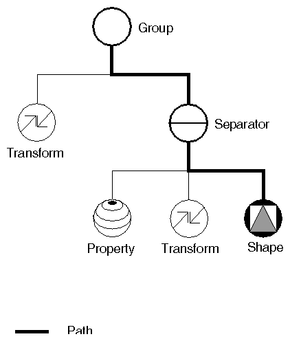
An ordered collection of nodes is referred to as a scene graph. (Figure 1-3 shows a simple scene graph. Figure In-1, in “About This Book,” has the key to the icons used in scene graph diagrams throughout this book.) This scene graph is stored in the Inventor database. Inventor takes care of storing and managing the scene graph in the database. The database can contain more than one scene graph.
After you have constructed a scene graph, you can apply a number of operations or actions to it, including rendering, picking, searching, computing a bounding box, and writing to a file.
Classes of database primitives include shape nodes (for example, sphere, cube, cylinder, quad mesh), property nodes (for example, material, lighting model, textures, environment), and group nodes (for example, separator, level-of-detail, and switch). Other special database primitives are engines and sensors. Engines are objects that can be connected to other objects in the scene graph and used to animate parts of the scene or constrain certain parts of the scene in relation to other parts (see Chapter 13, “Engines”). A sensor is an object that detects when something in the database changes and calls a function supplied by the application. Sensors can respond to specified timing requirements (for example, “Do this every n seconds”) or to changes in the scene graph data (see Chapter 12, “Sensors”).
Node kits facilitate the creation of structured, consistent databases. Each node kit is a collection of nodes with a specified arrangement. A template associated with the node kit determines which nodes can be added when necessary and where they should be placed. For example, the SoShapeKit node kit is used for any Inventor shape object. If you use this node kit, you don't have to create and arrange each node individually. By default, the template for the SoShapeKit contains an SoCube node, and it allows a material, geometric transformation, and other properties to be inserted in the correct place when required.
Another use of node kits is to define application-specific objects and semantics. For example, a flight-simulation package might include a variety of objects representing airplanes. Each of these airplanes consists of the same general scene graph structure—for example, fuselage, wings, and landing gear—as well as some airplane-specific methods—for example, bankLeft(), raiseLandingGear(). To an application writer using this package, each type of airplane can be dealt with in a similar way. There is no need to know the details of the structure of the subgraph representing the landing gear to raise it, since the general method, raiseLandingGear(), exists. Creating these new objects and methods requires extending Open Inventor by subclassing, which is described in The Inventor Toolmaker. It is highly recommended that you use some form of node kits in your application to maintain order and policy.
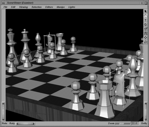
A manipulator is a special kind of node that reacts to user interface events and can be edited directly by the user. Manipulators typically have parts that render in the scene and provide a means for translating events into changes to the database. An example of a manipulator is the handle box, which is a bounding box of another object with handles at the corners and sides. In Figure 1-4, handle boxes surround the knights. By picking on a handle and dragging it, the user can change the scale or position of the box and thus the object inside it. Manipulators provide an easy way for applications to incorporate direct 3D interaction.
The Inventor Component Library provides window-system support and integration with the X Window System. This library includes the following features:
The render area accepts an X event, translates it into an Inventor event, and then passes it to “smart” objects, such as manipulators, that may handle the event.
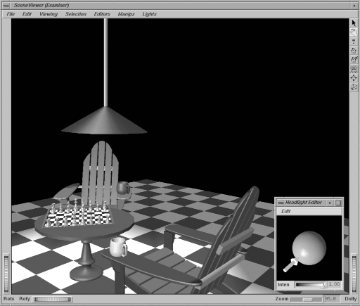
The Inventor Component Library also contains a set of viewers and editors that fall into the general category of components. Components are reusable modules that contain both a render area and a user interface. They are used for editing scene graph nodes (materials, lights, transformations) as well as for viewing scenes in different ways. Rather than solving the same problems over and over again, you can simply select an Inventor component and plug it into your application. If you need added functionality, you can write your own component and add it to Inventor (see The Inventor Toolmaker). Examples of components are the material editor, directional light editor (see Figure 1-5), fly viewer (“flies” through the scene), and examiner viewer (looks at a single object from any perspective).
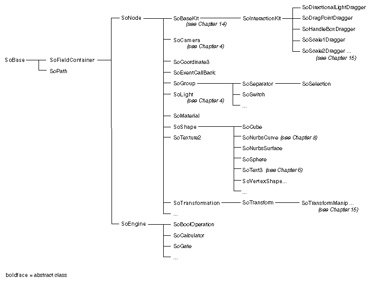
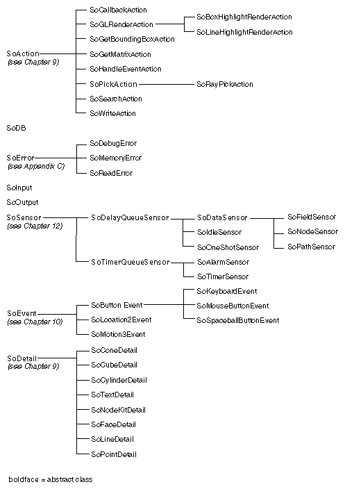
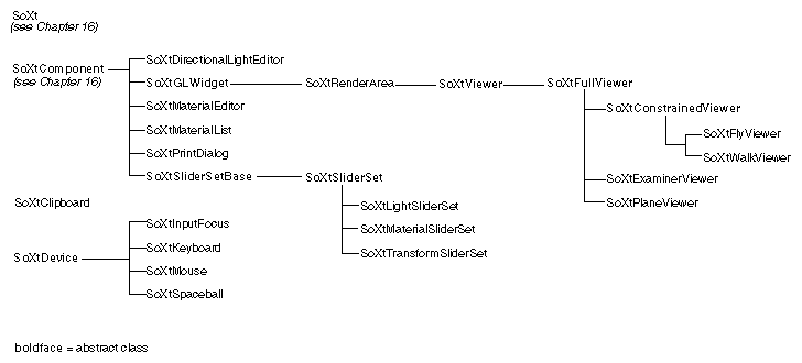
Figure 1-6 summarizes the Inventor class tree. Base classes are at the left, and derived classes are at the right. SoBase is the base class for SoFieldContainer, from which both nodes and engines are derived. Action classes are derived from SoAction. SoXtComponent is another base class. The Xt render area, as well as the viewers and editors, are all derived from SoXtComponent. Classes to the right in the tree inherit the fields and methods of the classes they are derived from.
One of the most important aspects of Inventor is the ability to program new objects and operations as extensions to the toolkit. One way to extend the set of objects provided by Inventor is to derive new classes from existing ones. See The Inventor Toolmaker for specific examples of creating new classes.
Another way to include new features in Inventor is by using callback functions, which provide an easy mechanism for introducing specialized behavior into a scene graph or prototyping new nodes without subclassing. A callback function is a user-written function that is called under certain conditions. Callback functions provided by Inventor include the following:
SoCallback—a generic node in the database that provides a callback function for all database actions (see Chapter 17, “Using Inventor with OpenGL”)
SoCallbackAction—generic traversal of the database with a callback function at each node (see Chapter 9, “Applying Actions”)
SoEventCallback—a node in the database that calls a user-defined function when it receives an event (see Chapter 10, “Handling Events and Selection”)
SoSelection—selection callback node (see Chapter 10, “Handling Events and Selection”)
Manipulators—provide callback functions for event processing
(see Chapter 15, “Draggers and Manipulators”)SoXt components—support their own callback functions when a change occurs (see Chapter 16, “Inventor Component Library”).
