Chapter Objectives
After reading this chapter, you'll be able to do the following:
Use a variety of shapes in the scene, including complex shapes that use information from coordinate and normal nodes
Explain how indexed shapes specify their own order for using coordinate, material, normal, and texture values
Experiment with different effects for color values, shininess, and transparency
Render a scene using different drawing styles for different parts of the scene
Render a scene using different light models
Create a scene with fog in it
Use the shape hints, complexity, and level-of-detail nodes to speed up performance
Experiment with different types of material and normal binding
For convenience, shapes are divided into two categories: simple shapes and complex shapes. Simple shapes are self-contained nodes that hold their own geometrical parameters. Complex shapes, in contrast, may refer to other nodes for their coordinates and normals. This chapter also discusses important property nodes, including material, draw-style, and lighting-
style nodes. Other chapter examples illustrate key concepts pertaining to geometric transformations and to binding nodes for materials and normals.
All shape nodes are derived from the abstract base class SoShape. Inventor provides the following simple shapes:
Cube (you specify the width, height, and depth)
Cone (you specify the height and bottom radius)
Sphere (you specify the radius)
Cylinder (you specify the height and the radius)
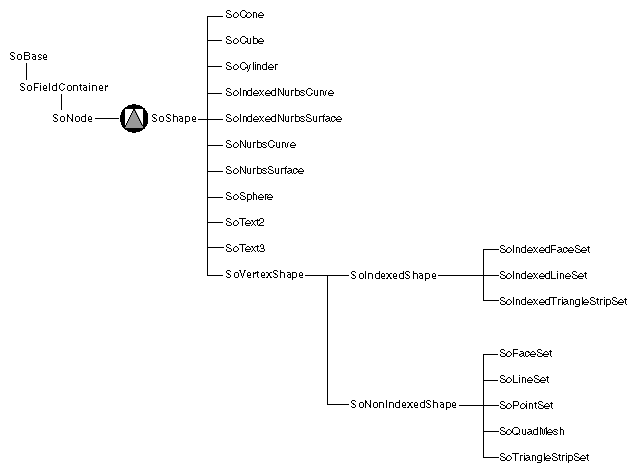
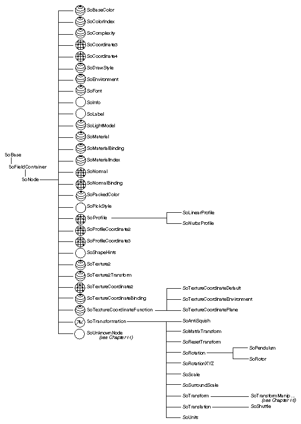
Figure 5-1 shows the portion of the class tree that contains shape classes.
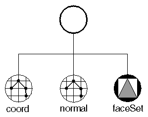
Complex shapes, such as triangle strip sets and face sets, require at least a set of coordinates. If the lighting is set to PHONG, complex shapes also require a set of surface normals, as shown in Figure 5-2. Coordinates and normals are defined by separate nodes in the scene graph so that this information can be shared by other nodes.
Examples of complex shapes include the following:
Face set, indexed face set
Line set, indexed line set
Triangle strip set, indexed triangle strip set
Point set
Quad mesh
NURBS curve and surface
An SoCoordinate3 node sets the current coordinates in the rendering state to the specified points. This node contains one field (point), which is of type SoMFVec3f. For example:
SbVec3f verts[6]; SoCoordinate3 *coord = new SoCoordinate3; // ...Initialize vertices array ... coord->point.setValues(0, 6, verts); |
An SoNormal node sets the current surface normals in the rendering state
to the specified vectors. This node contains one field, vector, of type SoMFVec3f.
 | Tip: Normals can also be generated automatically by Inventor, in which case you do not need an SoNormal node. See “Generating Normals Automatically” for further information. |
An SoFaceSet is a shape node that represents a polygonal object formed by constructing faces out of the current coordinates, current normals, current materials, and current textures. It uses the values within each node in the order they are given. (To use coordinates, normals, and materials in a different order, use the SoIndexedFaceSet node, described in the next section.)
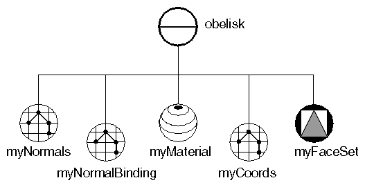
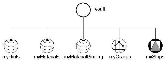
Example 5-1 creates an obelisk using a face set composed of eight faces. The scene graph for this example is shown in Figure 5-3. Ignore the normal binding node for now. This node is explained in “Binding Nodes”. “Face-Set Example”shows the image created by this example.
//  Eight polygons. The first four are triangles
//  The second four are quadrilaterals for the sides.
static float vertices[28][3] =
{
   { 0, 30, 0}, {-2,27, 2}, { 2,27, 2},            //front tri
   { 0, 30, 0}, {-2,27,-2}, {-2,27, 2},            //left  tri
   { 0, 30, 0}, { 2,27,-2}, {-2,27,-2},            //rear  tri
   { 0, 30, 0}, { 2,27, 2}, { 2,27,-2},            //right tri
   {-2, 27, 2}, {-4,0, 4}, { 4,0, 4}, { 2,27, 2},  //front quad
   {-2, 27,-2}, {-4,0,-4}, {-4,0, 4}, {-2,27, 2},  //left  quad
   { 2, 27,-2}, { 4,0,-4}, {-4,0,-4}, {-2,27,-2},  //rear  quad
   { 2, 27, 2}, { 4,0, 4}, { 4,0,-4}, { 2,27,-2}   //right quad
};

// Number of vertices in each polygon:
static long numvertices[8] = {3, 3, 3, 3, 4, 4, 4, 4};

// Normals for each polygon:
static float norms[8][3] =
{
   {0, .555,  .832}, {-.832, .555, 0}, //front, left tris
   {0, .555, -.832}, { .832, .555, 0}, //rear, right tris
   {0, .0739,  .9973}, {-.9972, .0739, 0},//front, left quads
   {0, .0739, -.9973}, { .9972, .0739, 0},//rear, right quads
};

SoSeparator *
makeObeliskFaceSet()
{
   SoSeparator *obelisk = new SoSeparator();
   obelisk->ref();

   // Define the normals used:
   SoNormal *myNormals = new SoNormal;
   myNormals->vector.setValues(0, 8, norms);
   obelisk->addChild(myNormals);
   SoNormalBinding *myNormalBinding = new SoNormalBinding;
   myNormalBinding->value = SoNormalBinding::PER_FACE;
   obelisk->addChild(myNormalBinding);

   // Define material for obelisk
   SoMaterial *myMaterial = new SoMaterial;
   myMaterial->diffuseColor.setValue(.4, .4, .4);
   obelisk->addChild(myMaterial);

   // Define coordinates for vertices
   SoCoordinate3 *myCoords = new SoCoordinate3;
   myCoords->point.setValues(0, 28, vertices);
   obelisk->addChild(myCoords);

   // Define the FaceSet
   SoFaceSet *myFaceSet = new SoFaceSet;
   myFaceSet->numVertices.setValues(0, 8, numvertices);
   obelisk->addChild(myFaceSet);

   obelisk->unrefNoDelete();
   return obelisk;
}
|
An SoIndexedFaceSet node is a shape node that represents a polygonal object formed by constructing faces out of the current coordinates, using the current surface normals, current materials, and current texture. In contrast to the SoFaceSet node, this node can use those values in any order. This node class contains four fields with indices that specify the ordering:
| coordIndex (SoMFLong) |
| |
| materialIndex (SoMFLong) |
| |
| normalIndex (SoMFLong) |
| |
| textureCoordIndex (SoMFLong) |
|
Be sure that the indices contained in the indexed face set can actually be found in the coordinates and normals lists, or errors will occur.
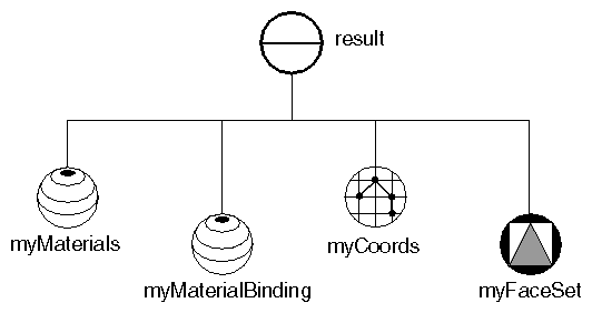
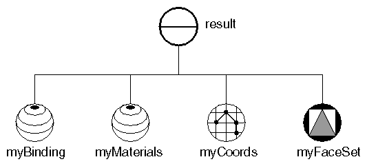
Example 5-2 creates the first stellation of the dodecahedron from an indexed face set. Each of the twelve intersecting faces is a pentagon. The scene graph diagram for this example is shown in Figure 5-4. “Indexed Face-Set Example” shows the image created by this example.
// Positions of all of the vertices:
//
static float vertexPositions[12][3] =
{
   { 0.0000,  1.2142,  0.7453},  // top

   { 0.0000,  1.2142, -0.7453},  // points surrounding top
   {-1.2142,  0.7453,  0.0000},
   {-0.7453,  0.0000,  1.2142},
   { 0.7453,  0.0000,  1.2142},
   { 1.2142,  0.7453,  0.0000},

   { 0.0000, -1.2142,  0.7453},  // points surrounding bottom
   {-1.2142, -0.7453,  0.0000},
   {-0.7453,  0.0000, -1.2142},
   { 0.7453,  0.0000, -1.2142},
   { 1.2142, -0.7453,  0.0000},

   { 0.0000, -1.2142, -0.7453}, // bottom
};
|
// Connectivity, information; 12 faces with 5 vertices each },
// (plus the end-of-face indicator for each face):

static long indices[72] =
{
   1,  2,  3,  4, 5, SO_END_FACE_INDEX, // top face

   0,  1,  8,  7, 3, SO_END_FACE_INDEX, // 5 faces about top
   0,  2,  7,  6, 4, SO_END_FACE_INDEX,
   0,  3,  6, 10, 5, SO_END_FACE_INDEX,
   0,  4, 10,  9, 1, SO_END_FACE_INDEX,
   0,  5,  9,  8, 2, SO_END_FACE_INDEX,

    9,  5, 4, 6, 11, SO_END_FACE_INDEX, // 5 faces about bottom
   10,  4, 3, 7, 11, SO_END_FACE_INDEX,
    6,  3, 2, 8, 11, SO_END_FACE_INDEX,
    7,  2, 1, 9, 11, SO_END_FACE_INDEX,
    8,  1, 5,10, 11, SO_END_FACE_INDEX,

    6,  7, 8, 9, 10, SO_END_FACE_INDEX, // bottom face
};

// Colors for the 12 faces
static float colors[12][3] =
{
   {1.0, .0, 0}, { .0,  .0, 1.0}, {0, .7,  .7}, { .0, 1.0,  0},
   { .7, .7, 0}, { .7,  .0,  .7}, {0, .0, 1.0}, { .7,  .0, .7},
   { .7, .7, 0}, { .0, 1.0,  .0}, {0, .7,  .7}, {1.0,  .0,  0}
};

// Routine to create a scene graph representing a dodecahedron
SoSeparator *
makeStellatedDodecahedron()
{
   SoSeparator *result = new SoSeparator;
   result->ref();

   // Define colors for the faces
   SoMaterial *myMaterials = new SoMaterial;
   myMaterials->diffuseColor.setValues(0, 12, colors);
   result->addChild(myMaterials);
   SoMaterialBinding *myMaterialBinding = new SoMaterialBinding;
   myMaterialBinding->value = SoMaterialBinding::PER_FACE;
   result->addChild(myMaterialBinding);

   // Define coordinates for vertices

   // Define coordinates for vertices
   SoCoordinate3 *myCoords = new SoCoordinate3;
   myCoords->point.setValues(0, 12, vertexPositions);
   result->addChild(myCoords);

   // Define the IndexedFaceSet, with indices into
   // the vertices:
   SoIndexedFaceSet *myFaceSet = new SoIndexedFaceSet;
   myFaceSet->coordIndex.setValues(0, 72, indices);
   result->addChild(myFaceSet);

   result->unrefNoDelete();
   return result;
}
|
The SoTriangleStripSet node constructs triangle strips out of the vertices located at the current coordinates. It is one of the fastest ways to draw polygonal objects in Inventor. The triangle strip set uses the current coordinates, in order, starting at the index specified by the startIndex field. (If no index is specified, it starts at the first index.)
The numVertices field indicates the number of vertices to use for each triangle strip in the set. The triangle strip set is described as follows:
static long numVertices[2] =
{
   32, // flag
   8   // pole
};
SoTriangleStripSet *myStrips = new SoTriangleStripSet;
myStrips->numVertices.setValues(0, 2, numVertices);
|
Because the numVertices field contains an array with two values, two triangle strips are created. The first strip (the flag) is made from the first 32 coordinate values. The second strip (the flagpole) is made from the next 8 coordinates. Face 0 determines the vertex ordering—in this case, counterclockwise.
Example 5-3 shows the code for creating a pennant-shaped flag. Figure 5-5 shows the scene graph for this example. “Triangle Strip Set Example” shows the resulting image.
// Positions of all of the vertices:

static float vertexPositions[40][3] =
{
   {  0,   12,    0 }, {   0,   15,    0},
   {2.1, 12.1,  -.2 }, { 2.1, 14.6,  -.2},
   {  4, 12.5,  -.7 }, {   4, 14.5,  -.7},
   {4.5, 12.6,  -.8 }, { 4.5, 14.4,  -.8},
   {  5, 12.7,   -1 }, {   5, 14.4,   -1},
   {4.5, 12.8, -1.4 }, { 4.5, 14.6, -1.4},
   {  4, 12.9, -1.6 }, {   4, 14.8, -1.6},
   {3.3, 12.9, -1.8 }, { 3.3, 14.9, -1.8},
   {  3,   13, -2.0 }, {   3, 14.9, -2.0},
   {3.3, 13.1, -2.2 }, { 3.3, 15.0, -2.2},
   {  4, 13.2, -2.5 }, {   4, 15.0, -2.5},
   {  6, 13.5, -2.2 }, {   6, 14.8, -2.2},
   {  8, 13.4,   -2 }, {   8, 14.6,   -2},
   { 10, 13.7, -1.8 }, {  10, 14.4, -1.8},
   { 12,   14, -1.3 }, {  12, 14.5, -1.3},
   { 15, 14.9, -1.2 }, {  15,   15, -1.2},

   {-.5, 15,   0 }, { -.5, 0,   0},   // the flagpole
   {  0, 15,  .5 }, {   0, 0,  .5},
   {  0, 15, -.5 }, {   0, 0, -.5},
   {-.5, 15,   0 }, { -.5, 0,   0}
};


// Number of vertices in each strip.
static long numVertices[2] =
{
   32, // flag
   8   // pole
};

// Colors for the 12 faces
static float colors[2][3] =
{
   { .5, .5,  1 }, // purple flag
   { .4, .4, .4 }, // grey flagpole
};

// Routine to create a scene graph representing a pennant.
SoSeparator *
makePennant()
{
   SoSeparator *result = new SoSeparator;
   result->ref();

   // A shape hints tells the ordering of polygons.
   // This ensures double-sided lighting.
   SoShapeHints *myHints = new SoShapeHints;
   myHints->vertexOrdering = SoShapeHints::COUNTERCLOCKWISE;
   result->addChild(myHints);

   // Define colors for the strips
   SoMaterial *myMaterials = new SoMaterial;
   myMaterials->diffuseColor.setValues(0, 2, colors);
   result->addChild(myMaterials);
   SoMaterialBinding *myMaterialBinding = new SoMaterialBinding;
   myMaterialBinding->value = SoMaterialBinding::PER_PART;
   result->addChild(myMaterialBinding);

   // Define coordinates for vertices
   SoCoordinate3 *myCoords = new SoCoordinate3;
   myCoords->point.setValues(0, 40, vertexPositions);
   result->addChild(myCoords);

   // Define the TriangleStripSet, made of two strips.
   SoTriangleStripSet *myStrips = new SoTriangleStripSet;
   myStrips->numVertices.setValues(0, 2, numVertices);
   result->addChild(myStrips);

   result->unrefNoDelete();
   return result;
}
|
The SoQuadMesh node constructs quadrilaterals from the vertices located at the current coordinates. It uses the coordinates in order, starting at the index specified by the startIndex field. (If no index is specified, it starts at the first index.)
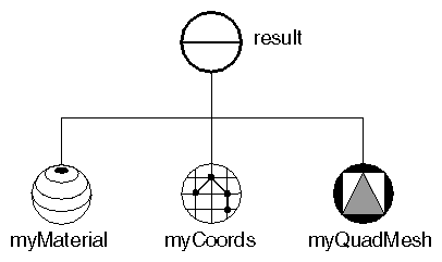
The verticesPerColumn and verticesPerRow fields indicate the number of vertices in the columns and rows of the mesh. Example 5-4 creates a quad mesh as follows:
SoQuadMesh *myQuadMesh = new SoQuadMesh; myQuadMesh->verticesPerRow = 12; myQuadMesh->verticesPerColumn = 5; |
Each row in this quad mesh contains 12 vertices. Each column contains 5 vertices. Figure 5-6 shows the scene graph for this example. “Quad Mesh Example” shows the resulting image.
// Positions of all of the vertices:

static float vertexPositions[160][3] =
{  // 1st row
   {-13.0,  0.0, 1.5}, {-10.3, 13.7, 1.2}, { -7.6, 21.7, 1.0},
   { -5.0, 26.1, 0.8}, { -2.3, 28.2, 0.6}, { -0.3, 28.8, 0.5},
   {  0.3, 28.8, 0.5}, {  2.3, 28.2, 0.6}, {  5.0, 26.1, 0.8},
   {  7.6, 21.7, 1.0}, { 10.3, 13.7, 1.2}, { 13.0,  0.0, 1.5},
   // 2nd row
   {-10.0,  0.0, 1.5}, { -7.9, 13.2, 1.2}, { -5.8, 20.8, 1.0},
   { -3.8, 25.0, 0.8}, { -1.7, 27.1, 0.6}, { -0.2, 27.6, 0.5},
   {  0.2, 27.6, 0.5}, {  1.7, 27.1, 0.6}, {  3.8, 25.0, 0.8},
   {  5.8, 20.8, 1.0}, {  7.9, 13.2, 1.2}, { 10.0,  0.0, 1.5},
   // 3rd row
   {-10.0,  0.0,-1.5}, { -7.9, 13.2,-1.2}, { -5.8, 20.8,-1.0},
   { -3.8, 25.0,-0.8}, { -1.7, 27.1,-0.6}, { -0.2, 27.6,-0.5},
   {  0.2, 27.6,-0.5}, {  1.7, 27.1,-0.6}, {  3.8, 25.0,-0.8},
   {  5.8, 20.8,-1.0}, {  7.9, 13.2,-1.2}, { 10.0,  0.0,-1.5},
   // 4th row
   {-13.0,  0.0,-1.5}, {-10.3, 13.7,-1.2}, { -7.6, 21.7,-1.0},
   { -5.0, 26.1,-0.8}, { -2.3, 28.2,-0.6}, { -0.3, 28.8,-0.5},
   {  0.3, 28.8,-0.5}, {  2.3, 28.2,-0.6}, {  5.0, 26.1,-0.8},
   {  7.6, 21.7,-1.0}, { 10.3, 13.7,-1.2}, { 13.0,  0.0,-1.5},
   // 5th row
   {-13.0,  0.0, 1.5}, {-10.3, 13.7, 1.2}, { -7.6, 21.7, 1.0},
   { -5.0, 26.1, 0.8}, { -2.3, 28.2, 0.6}, { -0.3, 28.8, 0.5},
   {  0.3, 28.8, 0.5}, {  2.3, 28.2, 0.6}, {  5.0, 26.1, 0.8},
   {  7.6, 21.7, 1.0}, { 10.3, 13.7, 1.2}, { 13.0,  0.0, 1.5}
};

// Routine to create a scene graph representing an arch.
SoSeparator *
makeArch()
{
   SoSeparator *result = new SoSeparator;
   result->ref();

   // Define the material
   SoMaterial *myMaterial = new SoMaterial;
   myMaterial->diffuseColor.setValue(.78, .57, .11);
   result->addChild(myMaterial);

   // Define coordinates for vertices
   SoCoordinate3 *myCoords = new SoCoordinate3;
   myCoords->point.setValues(0, 60, vertexPositions);
   result->addChild(myCoords);

   // Define the QuadMesh.
   SoQuadMesh *myQuadMesh = new SoQuadMesh;
   myQuadMesh->verticesPerRow = 12;

   myQuadMesh->verticesPerColumn = 5;
   result->addChild(myQuadMesh);

   result->unrefNoDelete();
   return result;
}
|
This section describes a number of important property classes, all of which are derived from SoNode:
SoMaterial, which sets the ambient color, diffuse color, specular color, emissive color, shininess, and transparency of the current material
SoDrawStyle, which tells shape nodes which drawing technique to use during rendering
SoLightModel, which tells shape nodes how to compute lighting calculations during rendering
SoEnvironment, which allows you to simulate various atmospheric effects, such as fog, haze, pollution, and smoke, and to describe other global environmental attributes such as ambient lighting and light attenuation
SoShapeHints, which provides additional information regarding vertex shapes to allow Inventor to optimize certain rendering features
SoComplexity, which allows you to specify the extent to which shape objects are subdivided into polygons, as well as the general degree of texture complexity and level of detail
SoUnits, which allows you to define a standard unit of measurement for all subsequent shapes in the scene graph
Each of these classes affects different elements of the rendering state, as described later in this section. Figure 5-7 shows the portion of the class tree for property nodes.
An SoMaterial node includes the following fields:
An example of setting values in an SoMaterial node is the following:
SoMaterial *gold = new SoMaterial; //Set material values gold->ambientColor.setValue(.3, .1, .1); gold->diffuseColor.setValue(.8, .7, .2); gold->specularColor.setValue(.4, .3, .1); gold->shininess = .4; |
Since gold is opaque, you can use the default value of 0.0 for the transparency field.
SoBaseColor, another class derived from SoNode, replaces only the diffuse color field of the current material and has no effect on other material fields.
| Tip: If you are changing only the diffuse color of an object, use an SoBaseColor node in place of an SoMaterial node. For example, to represent a complex terrain that uses many different diffuse colors, use one SoMaterial node for the ambient, specular, and emissive color values, and then use one SoBaseColor node with multiple values for the changing diffuse colors. The SoBaseColor class is also useful when the light model is BASE_COLOR (see “Light-Model Node”). |
An SoDrawStyle node includes the following fields:
| Tip: Draw-style LINES and POINTS look best with a BASE_COLOR lighting model. |
“Drawing Styles (FILLED, LINES, POINTS)” shows the same object rendered in different drawing styles.
An SoLightModel node includes the following field:
Figure In-5 and Figure In-6 show the same scene with the different lighting models. (Figure In-5 uses BASE_COLOR, and Figure In-6 uses PHONG.)
SoMaterial and SoBaseColor can be used along with any drawing style and any lighting model. In some cases, however, some of the material attributes might be ignored. For example, if you specify BASE_COLOR for the SoLightModel model field, only the diffuse color and transparency of the current material are used. But what happens if you specify only a base color (with SoBaseColor) and subsequently select the Phong lighting model for SoLightModel? In this case, Inventor uses the base color for the diffuse color and the default or current material element values for the other SoMaterial fields.
 | Note: By default, the light model is PHONG. For images to render correctly, you need to specify normals and light sources. If you want to see only colored objects, change the light model to BASE_COLOR and use SoBaseColor to specify only the base (diffuse) color. |
You can use the SoEnvironment node to simulate various atmospheric effects such as fog, haze, pollution, and smoke. For general purposes, these atmospheric effects are grouped under the term fog. The difference between fog and haze, for example, is simply the color and density.
Specifically, the SoEnvironment node allows you to specify the color and intensity of the ambient lighting, the light attenuation for point lights and spotlights, and the type, color, and visibility factor for fog. Figure In-7 shows the effects of an SoEnvironment node. This image uses a value of FOG for the fog type. The fogColor is (0.2, 0.2, 0.46).
An SoEnvironment node includes the following fields:
| Tip: For realistic scenes, clear the window to the fog color before drawing the fogged objects (see the SoXtRenderArea::setBackgroundColor() method.) |
By default, Inventor does not assume anything about how the vertices in a vertex shape are ordered, whether its surface is closed or open, or whether the faces of the shape are convex or concave. If you know that the vertices are in a consistent order, that the shape is closed, or that the shape faces are convex, you can use the SoShapeHints node to notify Inventor so that it can optimize certain rendering features.
The SoShapeHints node has four fields:
| vertexOrdering (SoSFEnum) |
| |
Values for this field are | ||
SoShapeHints::UNKNOWN_ORDERING | ||
| shapeType (SoSFEnum) |
| |
| faceType (SoSFEnum) |
| |
| creaseAngle (SoSFFloat) |
|
If the shapeType is SOLID and the vertexOrdering is either CLOCKWISE or COUNTERCLOCKWISE, Inventor turns on backface culling and turns off two-sided lighting. If the shapeType is not SOLID and the vertexOrdering is either CLOCKWISE or COUNTERCLOCKWISE, Inventor turns off backface culling and turns on two-sided lighting. In all other cases, backface culling and two-sided lighting are both off. If you use the SoShapeHints node, be sure to describe the object accurately; otherwise, objects may be rendered incorrectly.
Use the SoComplexity node to indicate the amount of subdivision into polygons for subsequent shape nodes in the scene graph. This node has three fields:
| type (SoSFEnum) |
| |
SoComplexity::OBJECT_SPACE | ||
| value (SoSFFloat) | | |
| textureQuality (SoSFFloat) |
|
“Specifying Different Levels of Complexity (left: OBJECT_SPACE; right: SCREEN_SPACE)” shows the same object with different levels of complexity. The spheres at the left use object-space complexity and a complexity value of .5. The spheres at the right use screen-space complexity and a complexity value of .06. The NURBS examples in Chapter 8 use the SoComplexity node.
Inventor lets you define your data in a variety of different units. It uses meters as its default units, but you can use the SoUnits node to specify a different unit of measurement. The units node acts like a scale node by scaling subsequent shapes into the specified units. SoUnits can adjust the amount it scales an object by checking to see if any other units have been defined. The units node adjusts the scale so that the previously defined units are no longer in effect.
The SoUnits node has one field:
| units (SoSFEnum) | defines the current unit of measurement to be applied to all subsequent shapes in the scene graph. Possible values are as follows: |
To render your data in units other than these, use an SoUnits node to set the current units back to meters, followed by a scale node that scales from meters into the desired units.
Materials and normals are bound to shape nodes in different ways. The first part of this discussion focuses on material binding, which is how the current materials specified in an SoMaterial node are mapped onto the geometry of the shape nodes that use that particular material. Since normal binding is analogous to material binding, this initial discussion focuses on material binding. (See Example 5-1 earlier in this chapter for an example of using a normal binding node.)
An SoMaterialBinding node contains a value that describes how to bind materials to shapes. These values include the following:
Each shape node interprets the binding type somewhat differently. For example, an SoSphere node does not have parts, faces, or indices, so those binding types (PER_PART, PER_FACE, PER_VERTEX) are meaningless for spheres. You can regard the value specified in the material-binding node as a hint to the shape about binding. If you specify a value that makes no sense for a particular shape, such as PER_FACE for a cylinder, the shape interprets the information the best it can (in this case, it uses OVERALL, since a cylinder has no faces). See the Open Inventor C++ Reference Manual for information on how each shape interprets the different binding types.
Suppose you specify PER_PART for a cylinder. The cylinder has three parts (sides, top, bottom). If the current material contains three values—for example, orange, purple, yellow—those values are used for the three parts of the cylinder, producing orange sides, a purple top, and a yellow bottom. But what happens if the number of current materials is greater than the number of parts? As you might guess, Inventor simply ignores the extra materials if they're not required. (If the current material list contains five values, your cylinder ignores the last two values.)
If the current material contains fewer values than the binding requires, Inventor cycles through the current values as often as needed. For example, if you specify PER_FACE for a cube and the current materials list contains three values (violet, periwinkle, teal), the results are as follows:
| Face 1 | violet | |
| Face 2 | periwinkle | |
| Face 3 | teal | |
| Face 4 | violet | |
| Face 5 | periwinkle | |
| Face 6 | teal |
So far, you've been using the values in the current material in order. You can, however, also use the current material values in a new order if you specify either PER_FACE_INDEXED or PER_VERTEX_INDEXED for an indexed vertex shape or PER_PART_INDEXED for a shape that has parts. When you use these types of binding, Inventor refers to the materials-index field of the shape node (for example, SoIndexedFaceSet, SoIndexedLineSet). Instead of starting with the first material and working through the list, Inventor indexes into the materials list in whatever order you specify.
As an example, consider a tetrahedron, represented as an SoIndexedFaceSet. The current materials list (in an SoMaterial node) contains the following values:
Material List
| 0 | peach | |
| 1 | khaki | |
| 2 | white |
and the materialIndex field (in an SoIndexedFaceSet node) contains these values:
Material Index
1
1
0
2
If you specify PER_FACE (not indexed), Inventor ignores the materialIndex field and cycles through the materials list in order:
| Face 1 | peach | |
| Face 2 | khaki | |
| Face 3 | white | |
| Face 4 | peach |
On the other hand, if you specify PER_FACE_INDEXED, Inventor uses the materialIndex field to pull values out of the materials list as follows:
| Face 1 | khaki | |
| Face 2 | khaki | |
| Face 3 | peach | |
| Face 4 | white |
This indexing is economical, since you can use a single, small set of materials for a wide variety of objects and purposes.
Inventor offers two types of per-vertex binding: PER_VERTEX and PER_VERTEX_INDEXED. With nonindexed material binding per vertex, Inventor simply selects materials in order from the materials list and assigns a material to each vertex of the shape node. It then interpolates the materials between the vertices and across the faces of the shape.
An SoMaterial node contains six fields, each of which holds multiple values. However, the number of values in these six fields may not be equal. You might have five different values in the ambient, diffuse, specular, and emissive fields, but only two values in the shininess field and one in the transparency field. In such cases, Inventor chooses a cycle equal to the field with the greatest number of values (in this case, five). In a field with fewer values, its last value is repeated until the end of the cycle.
When PER_VERTEX binding is specified, a value of -1 (the default) for the materialIndex field or the normalIndex field in an SoIndexedFaceSet (or any other indexed shape node) indicates to use the coordinate indices for materials or normals. The defined constants SO_END_LINE_INDEX, SO_END_FACE_INDEX, and SO_END_STRIP_INDEX can be used for this specification. This saves time and space and ensures that the indices match up. When you use a “special” coordinate index (such as SO_END_FACE_INDEX), the corresponding material index is skipped over so that the arrays of indices match.
Example 5-5 illustrates different types of material binding using the dodecahedron created in Example 5-2 (the common code has been omitted here). The scene graph for the example is shown in Figure 5-8. When you run the program, you can type a number to select the type of material binding, as follows:
0 for PER_FACE (see Figure In-8)
1 for PER_VERTEX_INDEXED (see Figure In-9)
2 for PER_FACE_INDEXED (see Figure In-10)
   // Which material to use to color the faces
   // half red & half blue
   static long materialIndices[12] = {
      0, 0, 0, 0, 0, 0,
      1, 1, 1, 1, 1, 1,
   };

   switch(whichBinding) {
     case 0:
       // Set up binding to use a different color for each face
       myBinding->value = SoMaterialBinding::PER_FACE;
       break;
     case 1:
       // Set up binding to use a different color at each
       // vertex, BUT, vertices shared between faces will
       // have the same color.
       myBinding->value = SoMaterialBinding::PER_VERTEX_INDEXED;
       break;
     case 2:
       myBinding->value = SoMaterialBinding::PER_FACE_INDEXED;
       myIndexedFaceSet->materialIndex.setValues(
                0, 12, materialIndices);
       break;
   }
Normals are bound to shapes in almost the same manner as materials. The type of normal binding specified in an SoNormalBinding node is a hint to the shape node about how to apply the current normals to that shape. Indexed shape nodes such as SoIndexedFaceSet and SoIndexedTriangle-
StripSet contain a normalIndex field used to store indices into the normals list (in an SoNormal node). If the type of binding specified does not require indices (for example, PER_VERTEX), the normalIndex field is not used.
The main difference between indexed normals and indexed materials is that indexed normals do not cycle. If used, normals must match up exactly with the faces, vertices, or parts of the object. If the normals do not match exactly, then default normals are generated (see the following section). You must specify enough normals to bind to faces, parts, or vertices.
Normals can be generated automatically for any shape derived from SoVertexShape. Because this process involves a great deal of computation, we recommend that you use automatic caching or explicitly turn on render caching so that the results are saved and can be reused (see Chapter 9 for more information on caching). Inventor generates normals automatically if needed for rendering and
DEFAULT normal binding is used and
You do not specify any normals or the number of normals is different from the number of vertices
When Inventor generates normals automatically, it looks at the creaseAngle field of the SoShapeHints node. The crease angle is defined as the angle between the normals for two adjoining faces. This angle indicates the maximum angle size at which separate normals are drawn for adjoining faces. For example, if the crease angle is one radian and the normals for two adjoining faces form an angle less than or equal to one radian, the faces share the same normal, which causes the edge to be shaded smoothly. If the normals for the faces form an angle greater than one radian, Inventor calculates separate normals for each face, which creates a crease. If you want an object to appear sharply faceted, specify 0 as the creaseAngle. If you want an object to appear completely smooth, specify PI as the creaseAngle.
Unlike other property nodes, transformation nodes do not replace the current geometric transformation element in the action state. Instead, they have a cumulative effect on the current geometric transformation. In Figure 5-9, for example, the transformations in node xfm1 are applied first, followed by the transformations in node xfm2.
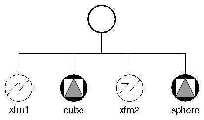
The cube is affected by only the transformation in xfm1. The sphere, however, is affected by both xfm1 and xfm2.
An SoTransform node includes the following fields:
Within each SoTransform node, the fields are applied so that the last field in the node (the center) affects the shape object first. The order is first the center, followed by the scale orientation, the scaling factor, the rotation, and the translation.
Figure 5-10 and “Effects of Ordering Transformation Fields” show how different ordering of transformations produces different results. At the left of , “Effects of Ordering Transformation Fields” the temple is scaled, rotated, and then translated. The transform node closest to the shape object affects the object first. You thus need to read backward through the code to see how the effects of the transformations are felt. At the right of , “Effects of Ordering Transformation Fields” the temple is rotated, then scaled and translated. Example 5-6 shows the code for the two sets of transformations.
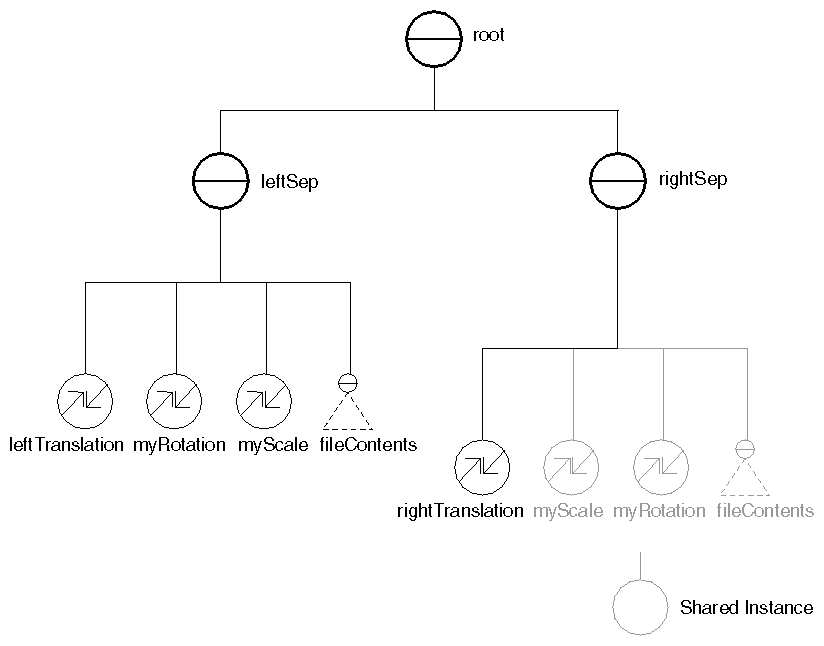
#include <Inventor/Xt/SoXt.h>
#include <Inventor/Xt/viewers/SoXtExaminerViewer.h>
#include <Inventor/SoDB.h>
#include <Inventor/nodes/SoMaterial.h>
#include <Inventor/nodes/SoRotationXYZ.h>
#include <Inventor/nodes/SoScale.h>
#include <Inventor/nodes/SoSeparator.h>
#include <Inventor/nodes/SoTranslation.h>

main(int, char **argv)
{
   // Initialize Inventor and Xt
   Widget myWindow = SoXt::init(argv[0]);
   if (myWindow == NULL) exit(1);

   SoSeparator *root = new SoSeparator;
   root->ref();

   // Create two separators, for left and right objects.
   SoSeparator *leftSep = new SoSeparator;
   SoSeparator *rightSep = new SoSeparator;
   root->addChild(leftSep);
   root->addChild(rightSep);
   // Create the transformation nodes.
   SoTranslation *leftTranslation  = new SoTranslation;
   SoTranslation *rightTranslation = new SoTranslation;
   SoRotationXYZ *myRotation = new SoRotationXYZ;
   SoScale *myScale = new SoScale;

   // Fill in the values.
   leftTranslation->translation.setValue(-1.0, 0.0, 0.0);
   rightTranslation->translation.setValue(1.0, 0.0, 0.0);
   myRotation->angle = M_PI/2;   // 90 degrees
   myRotation->axis = SoRotationXYZ::X;
   myScale->scaleFactor.setValue(2., 1., 3.);

   // Add transforms to the scene.
   leftSep->addChild(leftTranslation);   // left graph
   leftSep->addChild(myRotation);        // then rotated
   leftSep->addChild(myScale);           // first scaled

   rightSep->addChild(rightTranslation); // right graph
   rightSep->addChild(myScale);          // then scaled
   rightSep->addChild(myRotation);       // first rotated

   // Read an object from file. (as in example 4.2.Lights)
   SoInput myInput;
   if (!myInput.openFile("temple.iv"))
      return (1);
   SoSeparator *fileContents = SoDB::readAll(&myInput);
   if (fileContents == NULL) return (1);

   // Add an instance of the object under each separator.
   leftSep->addChild(fileContents);
   rightSep->addChild(fileContents);

   // Construct a renderArea and display the scene.
   SoXtExaminerViewer *myViewer =
            new SoXtExaminerViewer(myWindow);
   myViewer->setSceneGraph(root);
   myViewer->setTitle("Transform Ordering");
   myViewer->viewAll();
   myViewer->show();

   SoXt::show(myWindow);
   SoXt::mainLoop();
}
|