Chapter Objectives
After reading this chapter, you'll be able to do the following:
Build scene graphs using shape, property, and group nodes
Explain how nodes inherit values in the scene graph
Describe why separator nodes are useful
Explain the advantages of shared instancing of nodes in the scene graph
Define the term path and explain why paths are needed
Set and query field values
Ignore specified fields in a node
Explain how nodes are deleted in Open Inventor
Use Inventor's runtime type-checking mechanism
This chapter illustrates how to construct scene graphs from shape, property, and group nodes. It explains general rules for traversing a scene graph, focusing on GL rendering traversal. The concepts of database actions and traversal state are introduced.
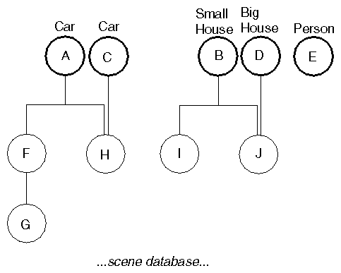
The Inventor scene database consists of information representing one or more 3D scenes. This database, SoDB, can contain several scene graphs, as shown in Figure 3-1. Each scene graph consists of a related set of 3D objects and attributes. In Figure 3-1, for example, the scene graphs might represent a car, a small house, another car, a large house, and a person.
You can perform two basic operations, or methods, directly on the scene database. First, you initialize it:
SoDB::init() |
This must be the first Inventor call you make. If you use the Inventor Component Library, the database is initialized automatically when you call SoXt::init() (see Chapter 16, “Inventor Component Library”). If you are not using components, but you are using interaction or node kits, or both, call SoInteraction::init(), which initializes the database, interaction, and node kits.
Second, you can read from a file into the scene database, which adds new scene graphs to it:
SoSeparator readAll(SoInput *in) or SbBool read(SoInput *in, SoNode *&rootNode) const |
or
SbBool read(SoInput *in, SoPath *&path) const
|
Using the first syntax, Inventor reads all graphs from a file specified by in and returns a pointer to a separator that contains the root nodes of all the scene graphs in the file. Using the second syntax, Inventor reads from a file specified by in and returns a pointer to the resulting root node (rootNode). Using the third syntax, Inventor reads a file specified by in and returns a pointer to the resulting path (path). (See “Paths”.) If an error occurs, the methods return FALSE. (Also see Chapter 11, “File Format” for more information on SoInput.)
A scene graph consists of one or more nodes, each of which represents a geometry, property, or grouping object. Hierarchical scenes are created by adding nodes as children of grouping nodes, resulting in a directed acyclic graph.
 | Note: Although Inventor nodes are organized into graphs, Inventor has no enforced policy on how the scene database is organized. You could, for example, create your own nodes that are organized into structures that are not graphs. (See The Inventor Toolmaker for more information on extending the Open Inventor toolkit.) |
Figure 3-1 shows a simple database containing five scene graphs. The top node of a scene graph is called a root node (nodes A through E). Notice how node H is connected to two different parent nodes. This is called shared instancing. Also note that node E is not connected to any other node in the database. Usually this is a temporary state, and the node is attached to other nodes as you build the scene graph.
A node is the fundamental element of a scene graph. It contains data and methods that define some specific 3D shape, property, or grouping. When a node is created, it is automatically inserted into the database as a root node. Usually, you connect the node to other nodes in the database to construct a hierarchy.
Nodes are divided into three basic categories:
These categories are not strict and are used only to help you learn about Inventor classes.
Use the new operator to create nodes. For example:
SoSphere *headSphere = new SoSphere; |
Do not allocate nodes in arrays. (See “How Nodes Are Deleted”.)
 | Note: Although you create nodes using the new operator, you cannot delete them using delete. See “How Nodes Are Deleted” for a description of how and when nodes are deleted in Inventor. An understanding of reference counting is vital to your use of Inventor, since you must be aware of the conditions under which a node is automatically deleted. |
Each node is composed of a set of data elements, known as fields, that describe the parameters of the node. For example, a point light-source node (of class SoPointLight) contains four fields: intensity, color, location, and on. The intensity field contains a value from 0.0 (no illumination) to 1.0 (maximum illumination). The color field specifies a Red/Green/Blue illumination color for the light source. The location field specifies the position of the light. The on field specifies whether the light is on.
Inventor defines a number of field types. Each field type has unique methods to get and set its values. Within each node, the fields are named according to their usage. For example, here are a few nodes and their fields:
Note that fields that contain multiple values, such as the point field in SoCoordinate3, have singular names.
Each node implements its own action behavior. When you want to perform a particular action on a scene, you create an instance of the action class (for example, SoGLRenderAction or SoGetBoundingBoxAction) and then apply it to the root node of the scene graph. For each action, the database manages a traversal state, which is a collection of elements or parameters in the action at a given time. Typically, executing an action involves traversing the graph from top to bottom and left to right. During this traversal, nodes can modify the traversal state, depending on their particular behavior for that action.
This chapter focuses on the OpenGL rendering action, since one of the primary reasons for constructing a 3D database is to view and manipulate
objects. The rendering traversal state consists of a set of elements, each of which can be altered by a given class of nodes. When a rendering action is applied, each element is used and interpreted in a specified manner. A few of the elements in the traversal state include the following:
Current geometric transformation
Current material components
Current lighting model
Current drawing style
Current text font
Current coordinates
Current normals
Current lights
Current viewing specification
An SoMaterial node, for example, sets the current values in the various material elements of the traversal state. An SoDrawStyle node sets the current value in the drawing-style element of the traversal state. Shape nodes, such as SoSphere, are especially important in rendering traversal, since they cause their shape to be drawn, using the current values in the traversal state.
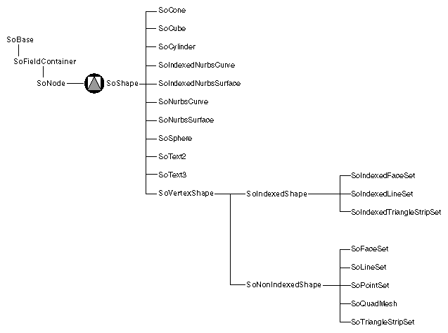
Shape nodes represent 3D geometric objects. They are unique because they describe physical matter that is affected by property and group nodes, and during a rendering action, they actually cause their shape to be drawn on the screen. Classes of shape nodes include SoSphere, SoIndexedFaceSet, and SoText3. Figure 3-2 shows the portion of the class tree that contains the shape-node classes.
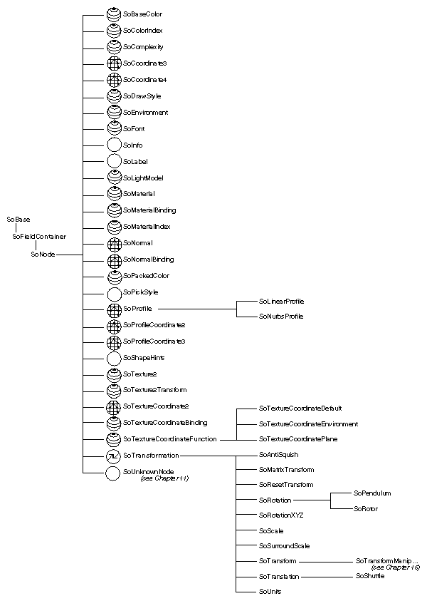
Property nodes represent appearance and qualitative characteristics of the scene, such as surface material, drawing style, or geometric transformation. Figure 3-3 shows the portion of the class tree that contains the property-node classes. Since property nodes fall naturally into several subgroupings, the scene graph diagrams use three different icons for property nodes:
The transform icon is used for nodes that perform transformations, such as SoTransform, SoRotation, SoScale, SoTranslation, SoRotationXYZ, and SoResetTransform. These nodes are all derived from SoTransformation.
The appearance icon is used forodes that modify an object's appearance, such as SoMaterial, SoMaterialBinding, SoBaseColor, SoComplexity, SoDrawStyle, SoLightModel, and SoFont.
The metrics icon is used for nodes that contain coordinate, normal, and other geometric information, such as SoCoordinate3, SoCoordinate4, SoProfileCoordinate2, SoProfileCoordinate3, SoNormal, and SoNormalBinding.
In general, a property node replaces the values in a corresponding element of the traversal state with its own new values. Geometric transformations are one exception to this rule. They concatenate with the current transformation.
Let's take the material node as an example. This node represents the surface and spectral (color) properties of an object. To create a bronze material, first create the material node and then set the field values appropriately:
SoMaterial *bronze = new SoMaterial; // set field values bronze->ambientColor.setValue(.33, .22, .27); bronze->diffuseColor.setValue(.78, .57, .11); bronze->specularColor.setValue(.99, .94, .81); bronze->shininess = .28; |
If you do not explicitly set the field values for a particular node, Inventor uses the default values for those fields (see the Open Inventor C++ Reference Manual for individual nodes). For example, in the preceding example, transparency remains 0.0.
SoTransform nodes, which produce geometric transformations, include fields for scaling, rotating, and translating. The following code defines a transform node that translates -1 in the y direction:
SoTransform *myXform = new SoTransform; // set field value myXform->translation.setValue(0.0, -1.0, 0.0); |
In order for this translation to take effect, it must be inserted appropriately into a scene graph (that is, before the shape node to translate).
A group node is a container for collecting child objects. Groups collect property, shape, and other group nodes into graphs. Figure 3-4 shows the portion of the class tree that contains the group-node classes. There are a variety of different group-node classes, each with a specialized grouping characteristic.
When a group node is created, it has no children. The base class for all group nodes is SoGroup, and all nodes derived from it have an addChild() method.
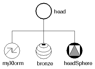
Suppose you want to combine the transform node, the material node, and the sphere node created earlier into a single group, the “head” group for a robot object. First, create the SoGroup. Then use the addChild() method for each child node, as follows:
SoGroup *head = new SoGroup; head->addChild(myXform); head->addChild(bronze); head->addChild(headSphere); |
Figure 3-5 shows a diagram of this group. All scene graph diagrams use the icons shown in Figure In-1. By convention, all figures show the first child in the group on the left, and ordering of children is from left to right.
The addChild() method adds the specified node to the end of the list of children in the group, as shown in the preceding code. Each child added to the group has an associated index. The first child in a group has an index of 0, the second child in a group has an index of 1, and so on.
void insertChild( SoNode *child, int newChildIndex);
|
inserts a child node into a group at the location specified by newChildIndex. For example,
SoDrawStyle *wireStyle; wireStyle = new SoDrawStyle; wireStyle->style = SoDrawStyle::LINES; // Insert as child 1 (the node right after the first child, // which is child 0. body->insertChild(wireStyle, 1); |
inserts a wireframe drawing-style node as the second child of the body group.
Other group methods allow you to find out how many children are in a group, to find the index of a particular child, to access the child with a given index, and to remove children.
Each node class has its own way of responding to a given database action. For this discussion, assume you are dealing only with the GL rendering action (here called simply rendering).
If the node to be rendered is a group node, it invokes the rendering action on each of its children in order, typically from left to right in the scene graph.
Each child node in turn executes its own rendering method, which then affects the traversal state in some way (see Chapter 9, “Applying Actions”). If the child node is a property node, it modifies one or more elements in the traversal state, such as the value used for diffuse color, the value used for scaling an object, or the value used for line width. Most property nodes simply replace the values for an element in the traversal state.
(A bronze material node replaces values in the material element with its own new values.) Geometric transformations are exceptions because they combine with each other to make composite transformations.If the child node is a shape node, it draws itself using the current traversal state.
During rendering, the scene graph is traversed, starting from the root node, from left to right and from top to bottom. Nodes to the right (and down) in the graph inherit the traversal state set by nodes to the left (and above).
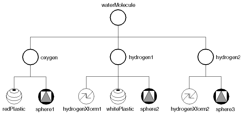
Figure 3-6 shows how nodes inherit state. When the waterMolecule node is rendered, it visits its first child, oxygen. The oxygen group then visits each of its children, as follows:
The material node (redPlastic) changes the material element to a shiny red surface.
The sphere node (sphere1) causes a sphere to be rendered using the current traversal state. A shiny red sphere is drawn at the origin.
The graph traversal continues to the next group on the right, hydrogen1, which in turn visits each of its children in order from left to right:
The transform node (hydrogenXform1) modifies the transformation matrix (let's say it scales by a factor of 0.75 in x, y, and z). It also modifies the transformation matrix by adding a translation of 0.0, -1.2, 0.0 (in x, y, and z).
The material node (whitePlastic) changes the material element to a shiny white surface.
The sphere node (sphere2) causes another sphere to be rendered using the modified traversal state. This sphere is white. Additionally, sphere2 appears in a new location and is scaled down in size, the result of the SoTransform node in its group.
Next, the hydrogen2 group visits its children, from left to right:
The transform node (hydrogenXform2) modifies the transformation matrix, translating in the +x and +y directions.
The sphere node (sphere3) causes the third sphere to be rendered using the modified traversal state. This sphere is still white and scaled by 0.75 because it inherits these attributes from the hydrogen1 group.
Example 3-1 shows the code to create this molecule.
// Construct all parts SoGroup *waterMolecule = new SoGroup; // water molecule SoGroup *oxygen = new SoGroup; // oxygen atom SoMaterial *redPlastic = new SoMaterial; SoSphere *sphere1 = new SoSphere; SoGroup *hydrogen1 = new SoGroup; // hydrogen atoms SoGroup *hydrogen2 = new SoGroup; SoTransform *hydrogenXform1 = new SoTransform; SoTransform *hydrogenXform2 = new SoTransform; SoMaterial *whitePlastic = new SoMaterial; SoSphere *sphere2 = new SoSphere; SoSphere *sphere3 = new SoSphere; // Set all field values for the oxygen atom redPlastic->ambientColor.setValue(1.0, 0.0, 0.0); redPlastic->diffuseColor.setValue(1.0, 0.0, 0.0); redPlastic->specularColor.setValue(0.5, 0.5, 0.5); redPlastic->shininess = 0.5; // Set all field values for the hydrogen atoms hydrogenXform1->scaleFactor.setValue(0.75, 0.75, 0.75); hydrogenXform1->translation.setValue(0.0, -1.2, 0.0); hydrogenXform2->translation.setValue(1.1852, 1.3877, 0.0); whitePlastic->ambientColor.setValue(1.0, 1.0, 1.0); whitePlastic->diffuseColor.setValue(1.0, 1.0, 1.0); whitePlastic->specularColor.setValue(0.5, 0.5, 0.5); whitePlastic->shininess = 0.5; // Create a hierarchy waterMolecule->addChild(oxygen); waterMolecule->addChild(hydrogen1); waterMolecule->addChild(hydrogen2); oxygen->addChild(redPlastic); oxygen->addChild(sphere1); hydrogen1->addChild(hydrogenXform1); hydrogen1->addChild(whitePlastic); hydrogen1->addChild(sphere2); hydrogen2->addChild(hydrogenXform2); hydrogen2->addChild(sphere3); |
To isolate the effects of nodes in a group, use an SoSeparator node, which is a subclass of SoGroup. Before traversing its children, an SoSeparator saves the current traversal state. When it has finished traversing its children, the SoSeparator restores the previous traversal state. Nodes within an SoSeparator thus do not affect anything above or to the right in the graph.
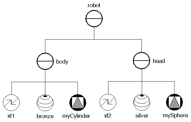
Figure 3-7, for example, shows the body and head for a robot. The body group, a separator, contains SoTransform and SoMaterial nodes that affect the traversal state used by the cylinder in that group. These values are restored when all children in the body group have been visited, so the head group is unaffected by the body-group nodes. Because the head group is also a separator group, the traversal state is again saved when group traversal begins and restored when group traversal finishes.
Separators are inexpensive to use and help to structure scene graphs. You will probably use them frequently.
 | Tip: The root node of a scene graph should be a separator if you want the state to be reset between successive renderings. |
Code for the robot body and head groups is shown below:
// create body parts SoTransform *xf1 = new SoTransform; xf1->translation.setValue(0.0, 3.0, 0.0); SoMaterial *bronze = new SoMaterial; bronze->ambientColor.setValue(.33, .22, .27); bronze->diffuseColor.setValue(.78, .57, .11); bronze->specularColor.setValue(.99, .94, .81); bronze->shininess = .28; SoCylinder *myCylinder = new SoCylinder; myCylinder->radius = 2.5; myCylinder->height = 6; // construct body out of parts SoSeparator *body = new SoSeparator; body->addChild(xf1); body->addChild(bronze); body->addChild(myCylinder); // create head parts SoTransform *xf2 = new SoTransform; xf2->translation.setValue(0, 7.5, 0); xf2->scaleFactor.setValue(1.5, 1.5, 1.5); SoMaterial *silver = new SoMaterial; silver->ambientColor.setValue(.2, .2, .2); silver->diffuseColor.setValue(.6, .6, .6); silver->specularColor.setValue(.5, .5, .5); silver->shininess = .5; SoSphere *mySphere = new SoSphere; // construct head out of parts SoSeparator *head = new SoSeparator; head->addChild(xf2); head->addChild(silver); head->addChild(mySphere); // add head and body SoSeparator *robot = new SoSeparator; robot->addChild(body); robot->addChild(head); |
In addition to SoSeparator, other subclasses of SoGroup include the following:
SoSelection (see Chapter 10, “Handling Events and Selection”)
In the robot example, SoSeparator nodes are used to contain the effects of nodes within a particular group in the scene graph; you do not want the head to inherit the transformation or material attributes from the body group. Conversely, the molecule example uses SoGroup nodes to accumulate a set of properties to apply to other nodes later in the graph.
An SoSwitch node is exactly like an SoGroup except that it visits only one of its children. It contains one field, whichChild, which specifies the index of the child to traverse. For example, the following code specifies to visit node c of switch s:
SoSwitch *s = new SoSwitch; s->addChild(a); // this child has an index of 0 s->addChild(b); // this child has an index of 1 s->addChild(c); // this child has an index of 2 s->addChild(d); // this child has an index of 3 s->whichChild = 2; // specifies to visit child(c) |
The default setting of whichChild is SO_SWITCH_NONE, which specifies to traverse none of the group's children.
You can use an SoSwitch node to switch between several different camera nodes for viewing a scene. You can also use an SoSwitch node for rudimentary animation. By cycling through a series of groups, you can, for example, make the wings on a duck flap up and down or make a robot walk across the screen. SoBlinker, derived from SoSwitch, cycles among its children (see Chapter 13, “Engines”) and provides some additional controls useful for animation.
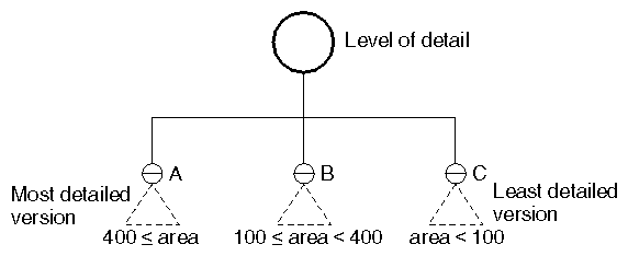
The SoLevelOfDetail node allows you to specify the same object with varying levels of detail. The children of this node are arranged from highest to lowest level of detail. The size of the objects when projected into the viewport determines which child to use. This node is very useful for applications requiring the fastest rendering possible. It has one field:
| screenArea (SoMFFloat) |
|
To determine which child to traverse, Inventor computes the 3D bounding box of all children in the level-of-detail group. It projects that bounding box onto the viewport and then computes the area of the screen-aligned rectangle that surrounds the bounding box. This area is then compared to the areas stored in the screenArea field. For example, Figure 3-8 shows a level-of-detail node with three children. Suppose the screenArea field contains the values [400.0, 100.0]. If the bounding-box projection of the group is 390.0 square pixels (that is, less than 400.0 but greater than 100.0), then childB is traversed. If the bounding-box projection of the group is 450.0 pixels (that is, greater than 400.0, then childA is traversed. If the bounding-box projection is less than 100.0, childC is traversed.
The SoComplexity node, discussed in Chapter 5, “Shapes, Properties, and Binding”, also affects the child selection for the level-of-detail node. If complexity is 0.0 or is of type BOUNDING_BOX, the last child in SoLevelOfDetail is always traversed. If complexity is 1.0, the first child is always used. If the complexity value is greater than 0.0 and less than 0.5, the computed size of the bounding rectangle is scaled down appropriately to use a less detailed representation. If the complexity value is greater than 0.5, the size of the bounding rectangle is scaled up appropriately. If the complexity is 0.5, Inventor uses the computed size of the bounding rectangle as is.
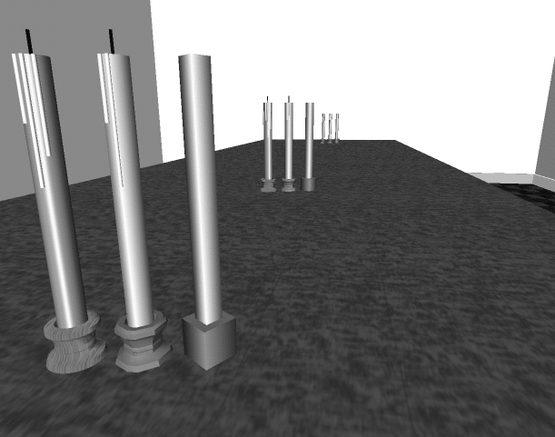
Figure 3-9 shows an object modeled with different levels of detail. Each group of candlesticks is arranged with the most detailed model at the left, a medium level of detail in the middle, and the least detailed model at the right. When the candlestick is close to the camera (as in the first group at the left of Figure 3-9), the most detailed model would be used. This model uses a texture on the base of the candlestick and has a detailed candle with a wick. When the object is farthest away, the least detailed model can be used since the details are not visible anyway. When the object is mid-range (the center group of Figure 3-9), the middle model would be used.
You can add any node to more than one group. A bicycle, for example, might use the same basic wheel group for both the front and rear wheels, with slight modifications for size and location of the two wheels. The term shared instancing refers to such cases, where a single node has more than one parent.
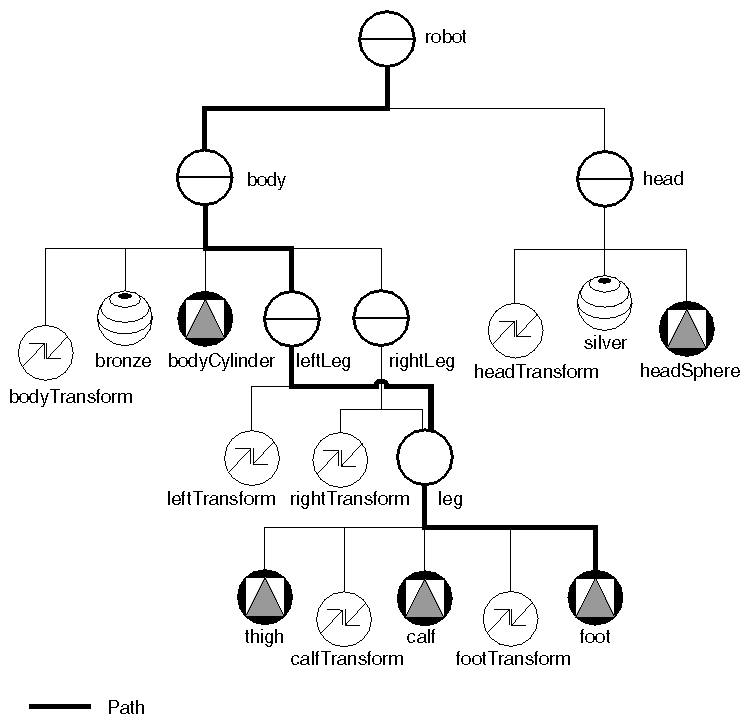
The robot example can instance the leg group twice to form a left and right leg, as shown in Figure 3-10. The basic leg group contains nodes for a cylinder (the thigh), a transformed cylinder (the calf), and a transformed cube (the foot). The left and right leg groups (the parents: rightLeg and leftLeg) each contain an additional SoTransform node to position the complete legs correctly onto the robot's body.
Any change made within the leg group is reflected in all instances of it. Here, for example, if the height of the cube in the foot node is doubled, both the left and right feet double in height.
Shared instancing offers database and program economy, since objects can be reused without duplicating them. You save both time and space by reusing nodes (and groups) when possible.
Do not, however, create cycles within a given scene graph. A node can connect to multiple parents but should not be a child of itself or any of its descendants.
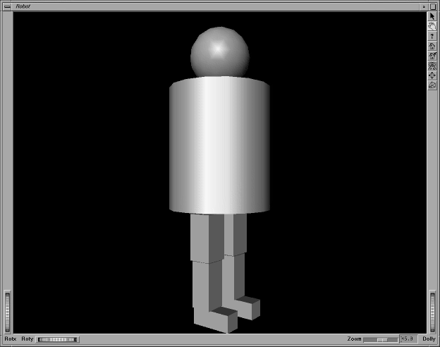
Example 3-2 shows the code for the robot as described up to this point. The rendered image is shown in Figure 3-11.
// Robot with legs // Construct parts for legs (thigh, calf and foot) SoCube *thigh = new SoCube; thigh->width = 1.2; thigh->height = 2.2; thigh->depth = 1.1; SoTransform *calfTransform = new SoTransform; calfTransform->translation.setValue(0, -2.25, 0.0); SoCube *calf = new SoCube; calf->width = 1; calf->height = 2.2; calf->depth = 1; SoTransform *footTransform = new SoTransform; footTransform->translation.setValue(0, -2, .5); SoCube *foot = new SoCube; foot->width = 0.8; foot->height = 0.8; foot->depth = 2; // Put leg parts together SoGroup *leg = new SoGroup; leg->addChild(thigh); leg->addChild(calfTransform); leg->addChild(calf); leg->addChild(footTransform); leg->addChild(foot); SoTransform *leftTransform = new SoTransform; leftTransform->translation = SbVec3f(1, -4.25, 0); // Left leg SoSeparator *leftLeg = new SoSeparator; leftLeg->addChild(leftTransform); leftLeg->addChild(leg); SoTransform *rightTransform = new SoTransform; rightTransform->translation.setValue(-1, -4.25, 0); // Right leg SoSeparator *rightLeg = new SoSeparator; rightLeg->addChild(rightTransform); rightLeg->addChild(leg); // Parts for body SoTransform *bodyTransform = new SoTransform; bodyTransform->translation.setValue(0.0, 3.0, 0.0); SoMaterial *bronze = new SoMaterial; bronze->ambientColor.setValue(.33, .22, .27); bronze->diffuseColor.setValue(.78, .57, .11); bronze->specularColor.setValue(.99, .94, .81); bronze->shininess = .28; SoCylinder *bodyCylinder = new SoCylinder; bodyCylinder->radius = 2.5; bodyCylinder->height = 6; // Construct body out of parts SoSeparator *body = new SoSeparator; body->addChild(bodyTransform); body->addChild(bronze); body->addChild(bodyCylinder); body->addChild(leftLeg); body->addChild(rightLeg); // Head parts SoTransform *headTransform = new SoTransform; headTransform->translation.setValue(0, 7.5, 0); headTransform->scaleFactor.setValue(1.5, 1.5, 1.5); SoMaterial *silver = new SoMaterial; silver->ambientColor.setValue(.2, .2, .2); silver->diffuseColor.setValue(.6, .6, .6); silver->specularColor.setValue(.5, .5, .5); silver->shininess = .5; SoSphere *headSphere = new SoSphere; // Construct head SoSeparator *head = new SoSeparator; head->addChild(headTransform); head->addChild(silver); head->addChild(headSphere); // Robot is just head and body SoSeparator *robot = new SoSeparator; robot->addChild(body); robot->addChild(head); |
 | Tip: When constructing a complicated scene graph, you may want to define the graph using the Inventor file format (see Chapter 11, “File Format”) and read the graph from a file or from a string in memory. This approach can be easier and less error-prone than constructing the scene graph programmatically. |
Paths are used to isolate particular objects in the scene graph. Suppose you want to refer to the left foot of the robot. Which node in Figure 3-10 represents the left foot? You can't refer simply to the foot node, since that node is used for both the left and right feet. The answer is that the left foot is represented by the path, or chain, starting at the robot node (the root), and leading all the way down the graph to the foot node. Figure 3-12 indicates the path for the left foot node.
A path contains references to a chain of nodes, each of which is a child of the previous node. A path represents a scene graph or subgraph (part of a scene graph). In scene graph diagrams in this book, a path is represented by a heavy line that connects the chain of nodes.
Paths are returned by a picking or search action, and you can construct your own path. (See Chapter 9, “Applying Actions,” for a detailed description of interactive picking.) The user of an interactive application might click the mouse over an object on the screen, causing the object to be picked, and then perform an operation on that object—for example, moving it, changing its color, or deleting it. The selection node manages a list of paths as the currently selected objects.
All actions that can be performed on a node can also be performed on a path. These actions include calculating a bounding box and origin for the path, accumulating a transformation matrix for it, and writing the path to a file.
How you use the information included in a path depends on your application. You may use the whole path, or only part of the path. If your user clicks the mouse on the robot's left foot, is the user selecting the whole robot, the left leg, or just the left foot? (Perhaps one click selects the whole robot, and subsequent clicks select parts of the robot that are lower in the graph, such as the left leg and foot.)
When you create a node, its fields are already set to predefined values. Afterward, you can change the values in its fields directly. The syntax for setting the value of a field depends on the type of the field and whether it is a single-value or multiple-value field. The following example creates a drawing-style node and sets its fields:
SoDrawStyle *d = new SoDrawStyle; d->style.setValue(SoDrawStyle::LINES) ; d->lineWidth.setValue(3) ; d->linePattern.setValue(0xf0f0); |
The current drawing style is now nonfilled, dashed outlines, with a line width of 3 pixels. If you do not set the field values explicitly, Inventor uses the default values for that node. Default values for SoDrawStyle nodes are as follows:
| Field | Default Values | |
| style | SoDrawStyle::FILLED | |
| lineWidth | 1 | |
| linePattern | 0xffff (solid) |
pointSize 1
The following sections discuss setting and getting values for different types of fields. See also Chapter 13, “Engines,”, which discusses field-to-field connections as well as several special types of fields—global fields and trigger fields.
You may be wondering why Inventor nodes have fields instead of simple member variables. This section outlines a few of the mechanisms provided by fields. The Inventor Toolmaker provides additional background on these topics.
First, fields provide consistent methods for setting and inquiring values, as described in the following sections and in the Open Inventor C++ Reference Manual. Second, fields provide a mechanism for Inventor to detect changes to the database. Third, you can connect fields in one node to fields in another node, as described in Chapter 13, “Engines,”. Finally, fields provide a consistent and automatic way to read and write node values.
A single-value field has one value of a given type. Single-value fields include the letters SF in their class name. For example:
| SoSFBool | contains an SbBool | |
| SoSFFloat | contains a single float | |
| SoSFRotation |
| |
| SoSFName | contains an SbName | |
| SoSFColor | contains a single SbColor |
Single-value fields are used for nodes that have no use for arrays of values, such as a line pattern, a translation value, a rotation value, or a camera aspect ratio.
A multiple-value field contains an array of values. Multiple-value fields include the letters MF in their class name—for example, SoMFBool, SoMFFloat, SoMFVec3f, and SoMFColor. Multiple-value fields are used for coordinate points and normal vectors. They are also used for materials, so that you can assign different colors to different vertices. Most fields have both SF and MF forms. See the Open Inventor C++ Reference Manual for descriptions of fields within each node class.
The examples earlier in this chapter show how to declare and create nodes. This section provides additional examples of the syntax for setting and getting values for single-value fields within the nodes. (Most fields have a setValue() and getValue() method and can also use the = operator to set values.)
This first example sets the value in the height field of an SoOrthographicCamera node through use of the setValue() method. This field is of type SoSFFloat:
SoOrthographicCamera *cam = new SoOrthographicCamera; cam->height.setValue(1.); |
or
cam->height = 1.; // = operator has been defined for this field |
To get the value for this field, use the getValue() method:
float result = cam->height.getValue(); |
You can specify an SoSFVec3f field in several different formats. Each defines a 3D vector:
You can set it from a vector (an SbVec3f).
You can set it from three floats (either a vector or three separate values).
You can set it from an array of three floats.
The following examples show how to set values for SoSFVec3f fields.
An SoTransform node has a field, translation, which is an SoSFVec3f field that contains one value of type SbVec3f. The variable xform is a transform-node instance.
SoTransform *xform = new SoTransform; //(1) Setting the field from a vector SbVec3f vector; vector.setValue(2.5, 3.5, 0.0); xform->translation.setValue(vector); // or: xform->translation = vector; //(2a) Setting the field from a vector of three floats xform->translation.setValue(SbVec3f(2.5, 3.5, 0.0)); // or: xform->translation = SbVec3f(2.5, 3.5, 0.0); //(2b) Setting the field from three floats float x = 2.5, y = 3.5, z = 0.0; xform->translation.setValue(x, y, z); //(3) Setting the field from an array of three floats float floatArray[3]; floatArray[0] = 2.5; floatArray[1] = 3.5; floatArray[2] = 0.0; xform->translation.setValue(floatArray); |
Use the getValue() method to get values for a field. This example copies the vector, changes it, and copies it back:
SbVec3f t = xform->translation.getValue(); t[0] += 1.0; xform->translation.setValue(t); // or: xform->translation = t; |
A rotation field specifies a rotation in 3D space. Since an SbRotation represents rotation around an axis by an angle, you can set its value by specifying the axis and angle:
SbRotation r; SbVec3f axis(0., 1., 0.); float angle = M_PI; //from math.h r.setvalue(axis, angle); // or SbRotation r(SbVec3f(0., 1., 1.), M_PI); |
You can also define a rotation to rotate one direction vector into another, as follows:
SbRotation r(SbVec3f(0.0, 0.0, 1.0), SbVec3f(0.0, 1.0, 0.0)); |
To set the value of the rotation field of an SoTransform node:
SoTransform *xform = new SoTransform; xform ->rotation = r; |
You can also use setValue() to set the value of a rotation field and supply an axis and angle, a quaternion, or two vectors.
The = (assignment) operator can be used to set a field's value from another field of the same type. As with vectors, getValue() returns the value of the field.
 | Tip: If you want to specify a rotation as an axis/angle, you must pass an SbVec3f and a float. Passing four floats specifies a quaternion. |
The SoMaterial node contains the following fields:
| Field Name | Class | |
| ambientColor | SoMFColor | |
| diffuseColor | SoMFColor | |
| specularColor | SoMFColor | |
| emissiveColor | SoMFColor | |
| shininess | SoMFFloat | |
| transparency | SoMFFloat |
These examples show different styles for setting the fields of an SoMaterial node. The transparency field is of type SoMFFloat, so it contains one or more values of type float. The diffuseColor field is of type SoMFColor, so it contains one or more values of type SbColor. The syntax for setting multiple values in an SoMFFloat field is as follows:
nodeName->fieldName.setValues(starting index, number of values, pointer to array of values); |
For example:
SoMaterial *mtl; float vals[3]; vals[0] = 0.2; vals[1] = 0.5; vals[2] = 0.9; mtl->transparency.setValues(0, 3, vals); |
Space for the array is reallocated when necessary. The values are copied in from the array. An example of setting a multiple-value field that uses an Sb type is as follows:
SoMaterial *mtl; SbVec3f vals[3]; vals[0].setValue(1.0, 0.0, 0.0); vals[1].setValue(0.0, 1.0, 0.0); vals[2].setValue(0.0, 0.0, 1.0); mtl->diffuseColor.setValues(0, 3, vals); |
If you want to set only one value in an SoMFFloat field, you can use the following shorthand method:
nodeName->fieldName.setValue(value1);
|
For example:
mtl->transparency.setValue(.25); //or mtl->transparency = .25; |
This short method sets the number of values equal to 1 and sets the field to the specified value. However, it also throws away any subsequent values that were previously set in the array, so you should use it only to set the field to have one value. Use the longer method (setValues) or the set1Value() method if you want to change one value in the array and preserve the rest of the values.
You can use the [ ] operator to get a particular value within a multiple-value field as follows:
f = myMtl->transparency[13]; // get 14th value of array |
You can also create loops to access all values in the field:
for (i = 0; i < myMtl->transparency.getNum(); i++) {
      printf("transparency value %d is %g\n", i,
               myMtl->transparency[i]);
}
|
To insert values in the middle of a field:
float newValues[2]; newValues[0] = 0.1; newValues[1] = 0.2; // First, make space; after this, myMtl->transparency[10] // and myMtl->transparency[11] will have arbitrary values: myMtl->transparency.insertSpace(10, 2); // Set the space created to the right values: myMtl->transparency.setValues(10, 2, newValues); |
To delete values from a field:
// Delete myMtl->transparency[8] and myMtl->transparency[9]; // the values in myMtl->transparency[10] on up will be moved // down to fill in the missing space, and the transparency // array will have two fewer values. myMtl->transparency.deleteValues(8, 2); |
See the Open Inventor C++ Reference Manual for additional methods used to edit MF fields.
Every field has an Ignore flag associated with it. Use the setIgnored() method to set or reset the Ignore flag. When this flag is set, the field is disregarded. This flag enables you to ignore certain fields in a node and to use others. For example, to ignore the specular color field in a material node so the value is inherited from the previous material:
SoMaterial *bronze = new SoMaterial; bronze->ambientColor.setValue(.33, .22, .27); bronze->diffuseColor.setValue(.78, .57, .11); bronze->specularColor.setIgnored(TRUE); bronze->shininess = .28; |
To turn the Ignore flag off:
bronze->specularColor.setIgnored(FALSE); |
The isIgnored() method returns TRUE if the Ignore flag for this field is set:
if (bronze->specularColor.isIgnored()) {
   printf("Yes, specular is ignored\n");
}
|
Some fields are not inherited and are thus not affected by the Ignore flag. Examples of fields that are not inherited are the fields of shape nodes, light-source nodes, some groups, and cameras, as well as the fields in the SoEnvironment node. If you set the Ignore flag for a field whose values are not inherited, Inventor simply uses the field's default values.
Every node has an Override flag associated with it. The Override flag is a powerful mechanism typically used (sparingly) near the top of a scene graph. When this flag is set, any nodes of the same type encountered later in the graph are ignored even if they also have their Override flag set. For example, you might insert a line-style SoDrawStyle node at the top of a graph to ensure that the whole scene is drawn as wireframe objects, regardless of drawing styles specified lower in the scene graph. Use the setOverride() method to set and reset the Override flag. The isOverride() method returns the state of the Override flag.
For example:
// This function toggles the given draw-style node between
// overriding any other draw-style nodes below it in the scene
// graph, and not having any effect at all on the scene graph.
//
void
toggleWireframe(SoDrawStyle *myDrawStyle)
{
   if (myDrawStyle->isOverride()) {
      myDrawStyle->style.setIgnored(TRUE);
      myDrawStyle->setOverride(FALSE);
   } else {
      myDrawStyle->style = SoDrawStyle::LINES;
      myDrawStyle->style.setIgnored(FALSE);
      myDrawStyle->setOverride(TRUE);
   }
}
|
Normally, the Override flag is not used within a scene graph for modeling. Use it in applications where you need to specify a temporary change to the whole graph.
Setting the Override flag on a node whose field values are not inherited (for example, on a sphere with a radius of 7) has no effect on other nodes in the graph of that type.
Although nodes are created in the usual C++ fashion, the procedure for deleting nodes differs from the C++ style. The following discussion explains how a node counts references to itself and when these references are incremented and decremented. It outlines the proper procedure for unreferencing a node, which results in the node's deletion.
Each node stores the number of references made to that node within the database. There are several different types of references for nodes:
Engines also store a reference count (see Chapter 13, “Engines,”). This count is incremented when the output of an engine is connected to a field. You can also increment or decrement the reference count manually, by calling ref() or unref().
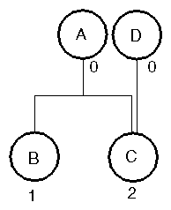
Figure 3-13 shows the reference counts for nodes in a small subgraph. Whenever you create a reference to a node, you increment its count. The action
A->addChild(B) |
adds node B to node A and also increments the reference count for node B by 1. In Figure 3-13 node C has a reference count of 2 because it has been added to two different parent groups. At this point, nodes A and D contain 0 references.
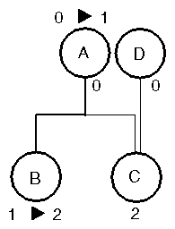
Referencing a node in a path also increments the node's reference count, as shown in Figure 3-14. The reference count for node A now becomes 1, and the reference count for node B becomes 2.
 | Tip: Be sure to reference the root of the scene graph: root->ref(). This node is not referenced by being a child of anything else. |
Inventor uses a reference-counting mechanism to delete nodes and subgraphs of nodes. To understand how nodes are deleted, you need to know how a node's reference count is incremented and decremented, as detailed in this section.
When you remove a reference to a node, its reference count is decremented. Removing a child decrements the reference count. When a node's count returns to 0, it is deleted from the database. Consider the following cases, however, where deleting a node causes problems (refer to Figure 3-13 for this discussion):
| Problem 1: | If you remove node B from node A, the reference count for node B goes to 0 and the node is deleted. But what if you still want to use node B? | |
| Problem 2: | How do you delete node A? Its reference count has always been 0. | |
| Problem 3: | What if someone applies an action to a node that has a reference count of 0? The action creates a path, which references the node. When the action finishes, the path is removed, and the node is deleted. |
The solution to these problems is that when you want to prevent a node from being deleted, you reference it:
B->ref(); |
Referencing a node increments its count by 1 and ensures that the node is not accidentally deleted. After you have explicitly referenced node B, you can safely remove it as a child of A without fear of deleting node B
(Problem 1).
Similarly, to prevent node A from being deleted (Problem 3), you
reference it:
A->ref(); |
If you want to delete A (Problem 2), you can unreference it, which decrements the reference count. Node A is now deleted, since you were the only one with a reference to it:
A->unref(); |
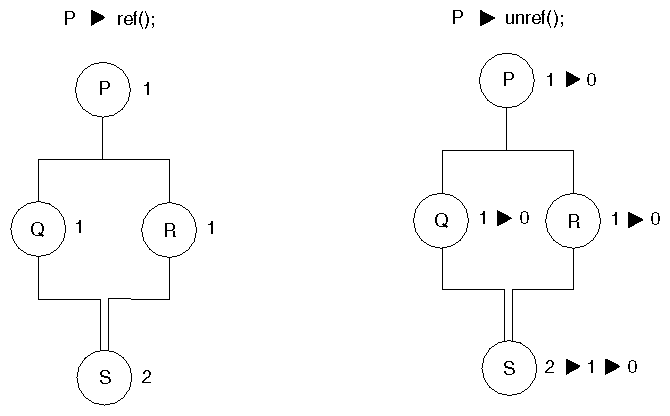
When a group is deleted, all of its children are removed and their reference counts are decremented by 1. In Figure 3-15, for example, if you specify
P->unref(); // reference count for P goes to 0 |
the reference counts for the child nodes are decremented as follows:
1. Q goes to 0
2. S goes to 1
3. R goes to 0
4. S goes to 0
Since all reference counts now equal 0, all nodes are deleted.
 | Tip: Do not allocate nodes, paths, or engines in arrays. This creates problems when one reference count goes to 0 and Inventor tries to free the space allocated for one object in the array. |
When you apply an action to a node, the action automatically creates a path that references the node. When the action finishes, it automatically removes the path, and thus decrements the node's reference count. Here again, if the node originally has a reference count of 0, it is deleted when the action finishes.
A node, path, or engine should be created only with new and never declared on the stack. These objects should be freed only when their reference count goes to 0, not when they go out of scope.
A newly created node has a reference count of 0. This does not mean that it immediately disappears, since a node is deleted only when the reference count is decremented to 0. Sometimes it is important to be able to restore a
node to its original state (that is, reference count equals 0, but it still exists). For example:
// Create a sphere of a certain radius and returns its bounding
// box. NOTE: BUGGY VERSION; provided for discussion only!

SoSphere *makeSphere(float radius, SbBox3f &box)
{
   sphere = new SoSphere;	// reference count of 0
   sphere->radius.setValue(radius);

   ba = new SoGetBoundingBoxAction;
   ba->apply(sphere);	// does a ref/unref
   box = ba->getBoundingBox();

   return  sphere;	 // ERROR! returning node that
	       // was deleted when ref count
	       // went back to zero!
}
|
In this example, the sphere node is referenced and unreferenced by SoGetBoundingBoxAction. When unreferenced, the sphere's reference count goes to 0, and it is deleted. The sphere needs to be referenced before the action is applied.
You can use the unrefNoDelete() method in cases such as this one, where you want to return the sphere to its original “fresh” state, with a reference count of 0 (but not deleted). Here is an example of using unrefNoDelete():
// Create a sphere of a certain radius and returns its bounding
// box. NOTE: CORRECT VERSION

SoSphere *makeSphere(float radius, SbBox3f &box)
{
   sphere = new SoSphere;	// reference count of 0
   sphere->ref();	// we want it to stay around
   sphere->radius.setValue(radius);

   ba = new SoGetBoundingBoxAction;
   ba->apply(sphere);	// does a ref/unref
   box = ba->getBoundingBox();

   sphere->unrefNoDelete();	// ref count goes to zero,
	// but sphere stays around
   return  sphere;	// returns sphere with ref
	// count of zero
}
|
Table 3-1 summarizes the occurrences that increment and decrement reference counts of nodes and engines. Note that connecting an engine to a field in a node does not increment the node's reference count. (Engines are discussed in Chapter 13.)
Table 3-1. References and Deletion
Increments Reference Count by 1 | Decrements Reference Count by 1 |
|---|---|
Adding a node as a child of another node increments child's reference count | Removing a node as a child of another node |
Adding a node to a path | Removing a node from a path |
Applying an action to a node or path increments reference count of all nodes that are traversed | When traversal for the action |
Adding a node to an SoNodeList node | Removing a node from an SoNodeList |
Setting an SoSFNode or SoMFNode value to point to a node | Changing an SoSFNode or SoMFNode value to point to a different node or to NULL, or deleting the value |
Connecting an output of an engine to a field in a node or engine increments the engine's reference count | Disconnecting an engine's output from the field decrements the engine's reference count |
Inventor provides runtime type-checking through the SoType class. Use the getTypeId() method on an instance to obtain the SoType for that instance. Runtime type-checking is available for most Inventor classes, including nodes, engines, actions, details, and events.
The SoType class has methods that enable you to find the parent class of a type (getParent()), to create an instance of a particular type (createInstance()), and to obtain an SbName for the class type (getName()). For example, the following code returns a name, such as
Material or Group, which you could then use to print some information about the node:
node->getTypeId().getName(); |
The following two statements both return the SoType for an SoMaterial node (the first is more efficient):
// (1)
SoMaterial::getClassTypeId();
// (2)
SoType::fromName("Material");
|
To determine whether an instance is of a particular type, use the == operator, as follows:
if (myNode->getTypeId() == SoGroup::getClassTypeId())
      // Is this an SoGroup?
|
To determine whether an instance is of the same type or derived from a particular class, use the isOfType() method or the SoType::derivedFrom() method (the two methods have the same effects):
// (1)
if (myNode->isOfType(SoGroup::getClassTypeId()))
   // Is this an SoGroup, SoSeparator, SoSwitch, and so on

// (2)
if (myNode->getTypeId().isDerivedFrom(
      SoGroup::getClassTypeId()))
|
Also see the description in Chapter 9 of the SoSearchAction, which allows you to search the scene graph for nodes of a particular type, or derived from a type.
You can assign a name to a node, path, or engine and then search for the object by name. Because the names are preserved when the objects are written to or read from files, they are also a useful way of identifying objects. The base class SoBase provides the setName() method, which allows you to specify a name for a node, path, or engine. It also provides the getName() method, which returns the name for the given object.
Any node, path, or engine has one name, which does not have to be unique. Names can be any SbName. An SbName can start with any uppercase or lowercase letter (A-Z) or an underscore (_). All characters in an SbName must be digits 0-9, upper/lowercase A-Z, or underscores. The default name for an object is the empty string ("").
Use the SoNode method getByName() to find a node or nodes with a given name. (SoPath and SoEngine provide similar getByName() methods.) The search action also allows you to search for an object or objects with a given name (see Chapter 9).
An example of how names might be used is a slot-car racer program that allows users to create their own slot cars, following simple conventions for how big the cars are, which direction is up, and how the standard nodes or engines in the slot cars are named. For example, the guidelines might specify that the SoTransform node that is the steering wheel's rotation is always named SteeringWheelRotation. The slot-car program could then read in the scene graph for a given car, search for the SteeringWheelRotation node, and then animate the steering wheel using that node.
Example 3-3 shows naming several nodes with setName(), then using getByName() to return specific nodes. The child node named MyCube is removed from the parent named Root.
